Desulfurization, denitration and dust removal equipment for flue gas of chemical plant

A technology for desulfurization, denitrification, and dust removal equipment, which is applied in gas treatment, chemical instruments and methods, and dispersed particle filtration. It can solve problems such as imperfect functions, poor environmental protection performance, and dust doping, and achieves simple structure and strong mechanical linkage. , The effect of high dust removal accuracy

Inactive Publication Date: 2021-11-05
安徽紫朔环境工程技术有限公司
View PDF6 Cites 0 Cited by
  • Summary
  • Abstract
  • Description
  • Claims
  • Application Information

AI Technical Summary

Problems solved by technology

[0004] The purpose of the present invention is to provide a flue gas desulfurization and denitration and dust removal equipment in chemical plants to solve the problem that the existing flue gas desulfurization and denitrification equipment in chemical plants is still doped with dust after desulfurization and denitrification, and the gas is directly discharged. Sometimes it will affect the environment, the environmental performance is poor, and the function is not perfect.

Method used


Image

  • Desulfurization, denitration and dust removal equipment for flue gas of chemical plant
  • Desulfurization, denitration and dust removal equipment for flue gas of chemical plant
  • Desulfurization, denitration and dust removal equipment for flue gas of chemical plant

Examples


Embodiment Construction

[0039] The present invention will be further described below in conjunction with the examples.

[0040] The following examples are used to illustrate the present invention, but cannot be used to limit the protection scope of the present invention. The conditions in the embodiment can be further adjusted according to the specific conditions, and the simple improvement of the method of the present invention under the premise of the concept of the present invention belongs to the protection scope of the present invention.

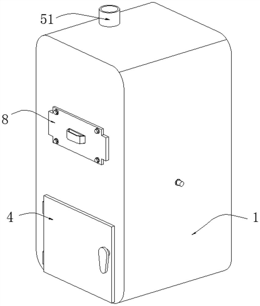
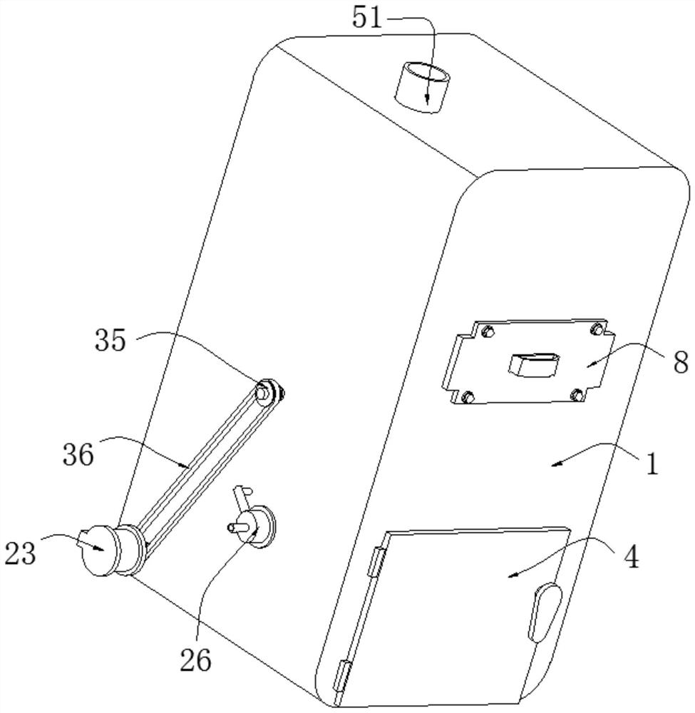
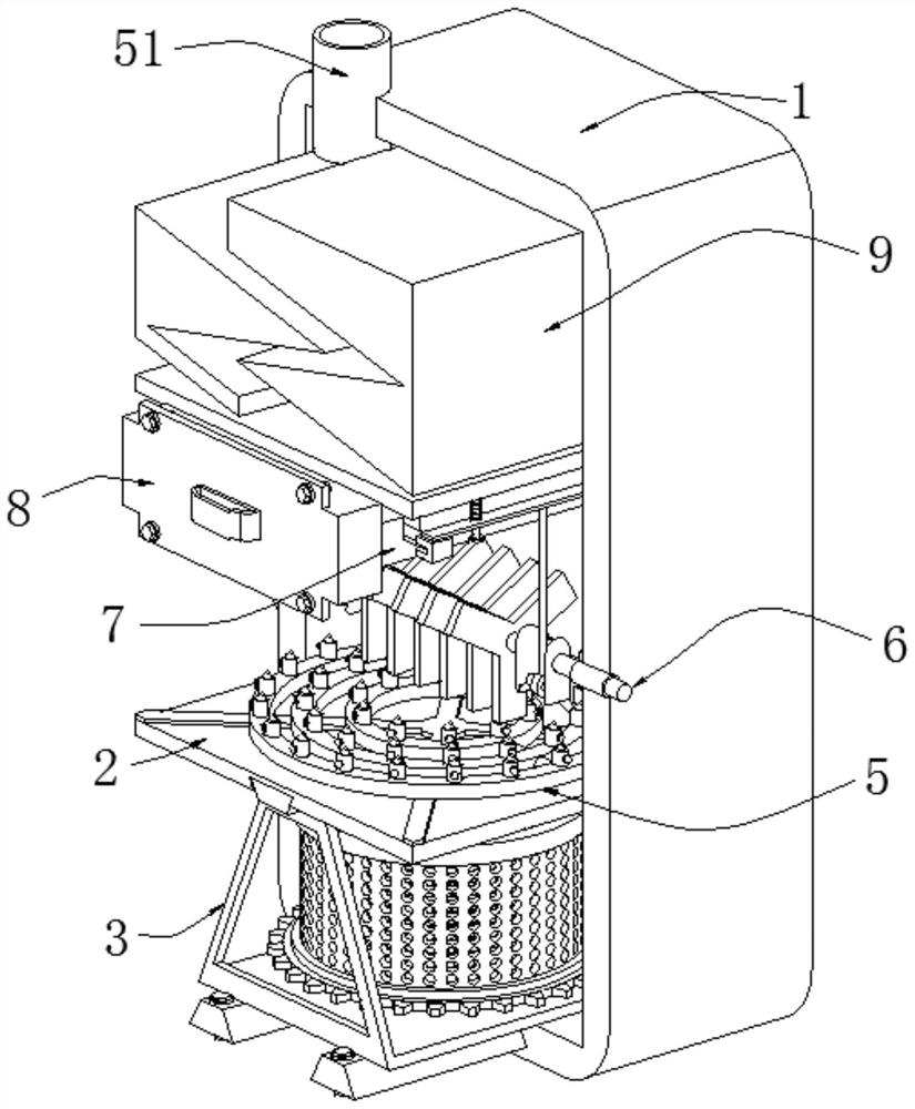
[0041] see Figure 1-10 , the present invention provides a flue gas desulfurization, denitrification and dust removal equipment in a chemical plant, which includes a housing 1 .

[0042] Two partitions 2 are installed inside the casing 1 one above the other and divide the casing 1 into three cavities from bottom to top, and the three cavities are respectively the first-level dust removal chamber and the second-level In the dust removal chamber and the drying...


PUM


Abstract

The invention discloses desulfurization, denitrification and dust removal equipment for flue gas of a chemical plant, and belongs to the technical field of chemical production, wherein the equipment comprises a shell, two partition plates and a rotary dust removal mechanism; the two partition plates are mounted in the shell up and down and divide the shell into three cavities from bottom to top, and the three cavities are respectively a first-stage dust removal cavity, a second-stage dust removal cavity and a drying cavity from bottom to top; and the rotary dust removal mechanism is arranged in the first-stage dust removal cavity and used for conducting first-stage dust removal treatment on the flue gas, and an operation door is hinged to the left side face of the shell. The two partition plates are arranged to divide the shell into the first-stage dust removal cavity, the second-stage dust removal cavity and the drying cavity, first-stage dust removal treatment is conducted through a coarse filter screen in the first-stage dust removal cavity, and second-stage dust removal treatment is conducted through water in the second-stage dust removal cavity in cooperation with flue gas sprayed out of a spray head and a fine filter screen; and a heating plate is matched with two flow guide seats to dry the gas, so that the flue gas can be effectively dedusted, the structure is simple, the use is convenient, and the dedusting precision is high.

Description

technical field [0001] The invention belongs to the technical field of chemical production, and in particular relates to a flue gas desulfurization, denitrification and dust removal equipment in a chemical plant. Background technique [0002] The chemical industry is the general term for enterprises and units engaged in the production and development of the chemical industry. The chemical industry penetrates all aspects and is an indispensable and important part of the national economy. Its development is to take the road of sustainable development, which has important practical significance for human economic and social development. The chemical industry occupies an important position in the national economy of various countries. It is the basic industry and pillar industry of many countries. The development speed and scale of the chemical industry have a direct impact on various sectors of the social economy. In the chemical production process, flue gas is often produced,...

Claims


Application Information

Patent Timeline
Patent Type & Authority Applications(China)
IPC IPC(8): B01D50/00B01D46/00B01D53/04B01D53/26
CPCB01D46/0056B01D46/0053B01D53/005B01D53/04B01D53/261B01D53/26B01D2258/0283
Inventor 孙正庭王洪明李树品项泽顺王魁
Owner 安徽紫朔环境工程技术有限公司
Why Eureka
Try Eureka