Compound die for cup punching for steel shell

A technology of shell punching cups and composite molds, which is applied in metal processing equipment, stripping devices, forming tools, etc., can solve the problems of unfavorable step-by-step stretching, large difference, and large moving distance of the binder ring 1.4, etc., and achieves easy control, Reliable material removal and the effect of eliminating the defects of the edge of the cup shell

Pending Publication Date: 2021-11-05
NINGBO GUANGHUA BATTERY
View PDF0 Cites 0 Cited by
  • Summary
  • Abstract
  • Description
  • Claims
  • Application Information

AI Technical Summary

Problems solved by technology

[0007] b. The relative movement distance of the pressing ring 1.4 is too large. Under the action of the pressing spring 1.7, the initial pressing force and the final pressing force are quite different, which often causes the edge of the cup shell to be pressed, which is not conducive to the subsequent multiple The station is further stretched step by step

Method used


Image

  • Compound die for cup punching for steel shell
  • Compound die for cup punching for steel shell
  • Compound die for cup punching for steel shell

Examples


Embodiment Construction

[0023] The present invention will be further described in detail below in conjunction with the accompanying drawings and embodiments.

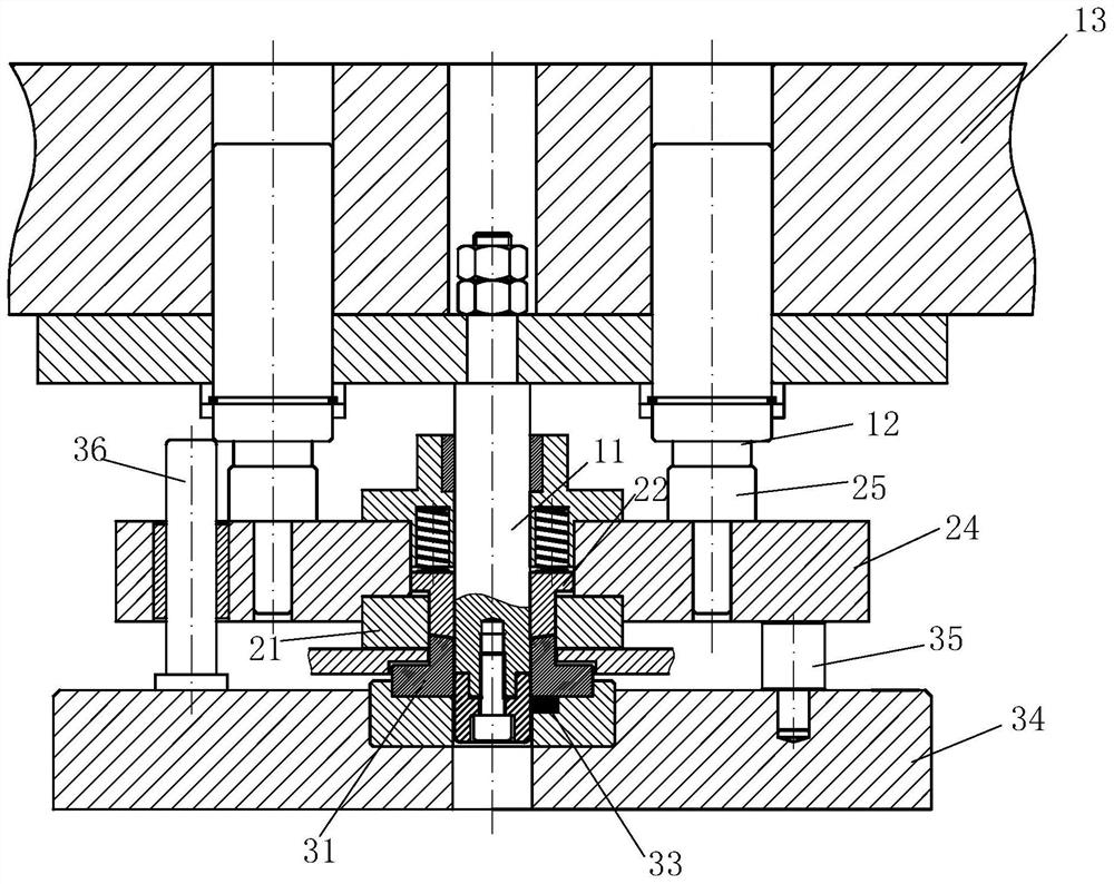
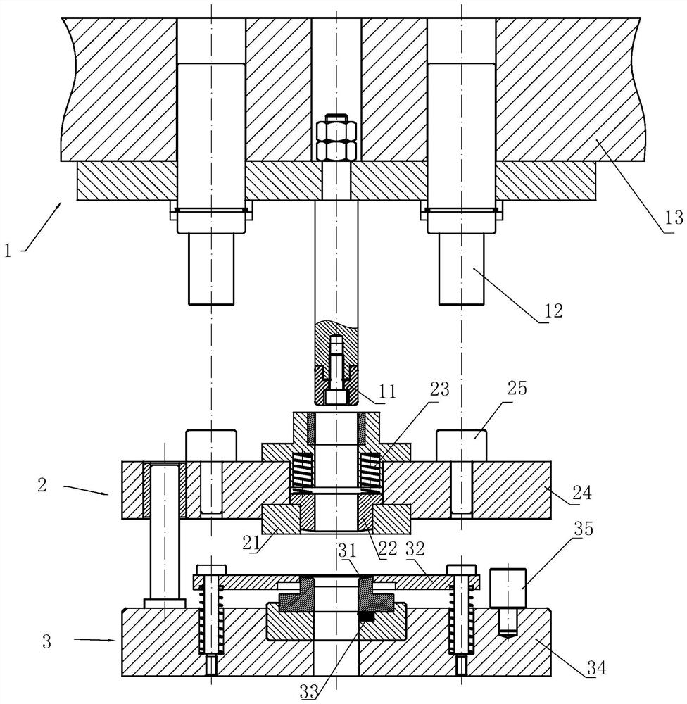
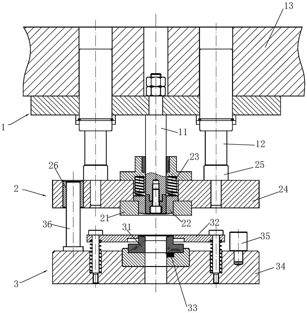
[0024] Such as Figure 1~3 As shown in the figure, a steel shell punching cup composite mold includes an upper mold part and a lower mold part 3, and the upper mold part is divided into two parts: a blanking upper mold 2 and a drawing upper mold 1, wherein the drawing upper mold 1 is fixed on a punching machine The bottom surface of the slider is located above the blanking upper die 2, and the blanking upper die 2 is located above the lower die part 3 and is connected to the lower die part 3 in a floating manner. Lower die part 3 comprises lower die 31, stripper plate 32, stripper 33 and lower die fixed plate 34, lower die 31, stripper plate 32, stripper 33 are installed on the lower die fixed plate 34 and fixed by the lower die Plate 34 is secured to the punch table. Blanking upper die 2 includes a blanking upper knife edge 21 , a pressing ...


PUM


Abstract

The invention discloses a compound die for cup punching for a steel shell. The compound die for cup punching for the steel shell comprises an upper die part and a lower die part, wherein the upper die part is divided into an upper die for blanking and an upper die for stretching, the upper die for stretching is fixed to the bottom surface of a punch press sliding block, the upper die for blanking is in floating connection with the lower die part, the lower die part comprises a lower die, a discharging plate and a stripping device, and the upper die for blanking comprises an upper knife edge for blanking, a pressing ring and a pressing spring; and the upper die for stretching comprises a stretching punch and a nitrogen spring, when the sliding block moves downwards, the upper die for stretching moves downwards, the nitrogen spring abuts against the upper die for blanking and pushes the upper die for blanking to move downwards, a limiting column is arranged on a lower die fixing plate, when the upper die for blanking moves downwards and abuts against the limiting column, the upper die for blanking and the lower die are matched to complete blanking and pressing, the sliding block continues moving downwards, the stretching punch completes stretching, and when the sliding block moves upwards, the stripping device completes stripping for the cup shell. The compound die for cup punching for the steel shell is reasonable in structure, can stably and reliably realize the four actions of blanking, pressing, stretching and stripping so as to realize a stable, reliable and continuous cup punching process, and can basically eliminate the defects of the rim of the cup shell and increase the production efficiency.

Description

technical field [0001] The invention belongs to the technical field of battery steel shell stamping, and relates to a cup punching die, in particular to a composite steel shell punching cup die, which is used for punching steel shells of alkaline zinc-manganese batteries. Background technique [0002] Alkaline battery steel case is made of thin steel strip through multi-station stretching. Usually, the first station completes blanking and first-stage stretching through a composite mold, referred to as punching cup. In fact, to complete the "blanking + stretching" action, there are four main actions in the extension: blanking, pressing, stretching, and stripping. At present, the domestic punch press industry is generally a single-slider general-purpose punch. In general, a composite mold is installed on a single-slider general-purpose punch to realize the four actions and realize continuous punching. The stability and reliability are not high, which is more typical at present...

Claims


Application Information

Patent Timeline
Patent Type & Authority Applications(China)
IPC IPC(8): B21D37/08B21D28/14B21D45/08
CPCB21D37/08B21D28/14B21D45/08
Inventor 忻琳浩周时健何俊文
Owner NINGBO GUANGHUA BATTERY
Why Eureka
Try Eureka