Square billet weighing, mark spraying and billet discharging system and method thereof

A spraying and weighing technology, which is applied in the direction of manufacturing tools, configuration of indicating equipment/measuring equipment, casting equipment, etc., to achieve improved efficiency, solve the problems of phosphorus removal and billet orientation, and speed up the rhythm of billet discharge

Active Publication Date: 2021-11-05
CHINA NAT HEAVY MACHINERY RES INSTCO
View PDF12 Cites 2 Cited by
  • Summary
  • Abstract
  • Description
  • Claims
  • Application Information

AI Technical Summary

Problems solved by technology

[0003] For this reason, the present invention proposes a system and method for billet weighing, spraying, and billet ejection, which are used to overcome the above-mentioned problems or at least partially solve or alleviate the above-mentioned problems

Method used


Image

  • Square billet weighing, mark spraying and billet discharging system and method thereof
  • Square billet weighing, mark spraying and billet discharging system and method thereof
  • Square billet weighing, mark spraying and billet discharging system and method thereof

Examples


Embodiment 1

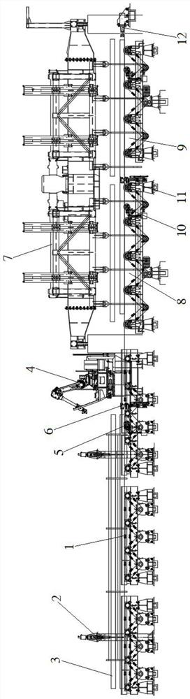
[0033] refer to figure 1 , the embodiment of the present invention proposes a billet weighing and spraying number ejection system, including: a conveying roller table 1, a number spraying machine 4, a billet roller table and a steel scooping machine 7; the conveying roller table 1 is used for conveying Casting slab 3, a weighing device 2 is arranged above the conveying roller table 1; the number spraying machine 4 is arranged at the end of the conveying roller table 1, and a weighing position detection device is arranged in front of the said number spraying machine 4 Device 5, the rear of the weighing position detection device 5 is provided with a lifting baffle 6; the billet roller table is arranged behind the number spraying machine 4; the steel scooping machine 7 is arranged on the billet roller above the road.

[0034] In order to weigh the slab, it is necessary to stop the slab 3 at the set position on the conveying roller table 1; a weighing position detection device 5 ...

Embodiment 2

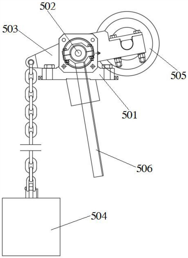
[0039] refer to figure 2 , on the basis of Embodiment 1, the weighing position detection device 5 includes: a shaft seat 501, a swing frame 503 and a swing rod 506; the shaft seat 501 is fixed on the conveying roller table 1, and the shaft seat 501 is provided with a rotating shaft 502; the swing frame 503 is arranged on the rotating shaft 502, a counterweight 504 is suspended at one end of the swing frame 503, and a roller 505 is provided at the other end of the swing frame 503; the swing rod 506 is vertically fixed at the end of the rotating shaft 502, and a detection switch is arranged on the movement track of the swing rod 506.

[0040] The counterweight 504 pulls one end of the oscillating frame 503 downward under the action of gravity, causing the other end of the oscillating frame 503 to tilt up, so that the roller 505 protrudes from the surface of the conveying roller table 1, and when the billet 3 moves to the roller 505, the roller 505 is pressed down , drive the r...

Embodiment 3

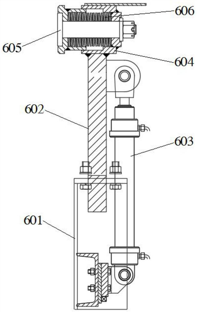
[0042] refer to image 3 , on the basis of Embodiment 2, the lifting baffle 6 includes: a base 601, a hydraulic cylinder 603 and a buffer seat 604; the base 601 is fixedly connected to the frame of the conveying roller table 1, and the base 601 The upper vertical sliding assembly is equipped with a riser 602; one end of the hydraulic cylinder 603 is connected to the base 601, and the other end is connected to the riser 602; the buffer seat 604 is fixed on the top of the riser 602 A buffer head 605 is slidably fitted in the buffer seat 604 , and a buffer spring 606 is arranged between the buffer head 605 and the buffer seat 604 .

[0043] When the lifting baffle 6 is raised, the hydraulic cylinder 603 extends upwards, driving the vertical plate 602 to rise, so that the buffer seat 604 and the buffer head 605 are at the same height as the casting slab 3 on the conveying roller table 1, when the casting slab 3 is moving in inertia After touching the buffer head 605, the buffer h...


PUM


Abstract

The invention provides a square billet weighing, mark spraying and billet discharging system. The system comprises a conveying roller way, a mark spraying machine, a billet discharging roller way and a steel fishing machine; the conveying roller way is used for conveying casting blanks, and a weight fixing device is arranged above the conveying roller way; the mark spraying machine is arranged at the tail end of the conveying roller way, a weighing position detection device is arranged in front of the mark spraying machine, and a lifting baffle is arranged behind the weighing position detection device; the billet discharging roller way is arranged behind the mark spraying machine; and the steel fishing machine is arranged above the billet discharging roller way. The invention further provides a square billet weighing, mark spraying and billet discharging method which is implemented by adopting the square billet weighing, mark spraying and billet discharging system.

Description

technical field [0001] The invention belongs to the field of metallurgical equipment, and in particular relates to a billet weighing and spraying number discharging system and method thereof. Background technique [0002] In order to optimize the cutting length of the slab, many steel mills currently use weighing equipment to feed back the weight to adjust the cutting length. At the same time, in order to facilitate the information tracking of the slab, online coding of the slab is adopted. In order to improve production efficiency and reduce the labor intensity of workers, some enterprises use robots for online spraying. However, in order to weigh and spray numbers, it is necessary to increase the residence time of each slab on the roller table, that is, to slow down the rhythm of the slab, and to increase the pressure of the slab, and it is necessary to reduce the casting speed to achieve these. Features. Moreover, in order to obtain a good spraying effect, the section ...

Claims


Application Information

Patent Timeline
Patent Type & Authority Applications(China)
IPC IPC(8): B22D11/12B22D2/00B22D11/128
CPCB22D11/1233B22D2/00B22D11/128Y02P70/10
Inventor 何保卫何博章裕琳李积文蒋军
Owner CHINA NAT HEAVY MACHINERY RES INSTCO
Why Eureka
Try Eureka