High-precision steel plate drilling equipment for orthopedics department

A high-precision, steel plate technology, applied in the direction of drilling/drilling equipment, metal processing equipment, manufacturing tools, etc., can solve the problems of inconvenient adjustment, inconvenient operation, low efficiency of steel plate drilling, etc., to avoid random spilling, Realize the effect of intelligent operation

Active Publication Date: 2021-11-05
南京市淑先科技有限公司
View PDF6 Cites 6 Cited by
  • Summary
  • Abstract
  • Description
  • Claims
  • Application Information

AI Technical Summary

Problems solved by technology

[0004] In order to overcome the shortcomings of traditional steel plate punching equipment for processing steel plates, which are inconvenient to adjust, inconvenient to operate, low in efficiency of steel plate punching, poor in quality of steel plate punching, and unsuitable for making high-precision orthopedic steel plates, the present invention Technical problem: To provide a high-precision steel plate drilling equipment for orthopedic use that is easy to adjust, simple to operate, and accurately drilled

Method used


Image

  • High-precision steel plate drilling equipment for orthopedics department
  • High-precision steel plate drilling equipment for orthopedics department
  • High-precision steel plate drilling equipment for orthopedics department

Examples


Embodiment 1

[0031] A high-precision steel plate hole-making equipment for orthopedics, such as Figure 1 to Figure 3 As shown, it includes a base 1, a first fixed frame 2, a second fixed frame 3, a cooling plate 4, a sliding glass door 5, a rodless cylinder 6, an electric drill 7, a supporting mechanism 8 and a moving mechanism 9, and the left side of the top of the base 1 There is a first fixed frame 2, the top of the first fixed frame 2 is provided with a cooling plate 4, the front side of the first fixed frame 2 is slidingly provided with a sliding glass door 5, and the left rear side of the upper inner wall of the first fixed frame 2 is provided with a rodless Cylinder 6, an electric drill 7 is provided on the telescopic rod of the rodless cylinder 6, a second fixed frame 3 is provided on the right side of the top of the base 1, a support mechanism 8 is provided at the bottom of the inner wall of the first fixed frame 2, and a moving mechanism is connected to the support mechanism 8 9...

Embodiment 2

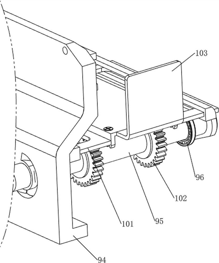
[0036] On the basis of Example 1, such as Figure 4 As shown, a correction mechanism 10 is also included. The correction mechanism 10 includes a second bracket 101, a first full gear 102 and a correction plate 103. The front part of the rotating shaft 95 is provided with the first full gear 102, and the rear side of the fixed splint 93 slides. A second bracket 101 is arranged in the formula, and the second bracket 101 is slidably connected with the sliding splint 94, and the left side of the second bracket 101 is provided with a correction plate 103.

[0037] The staff can drive the rotating shaft 95 to rotate by turning the handle, and the rotating shaft 95 rotates through the first full gear 102 to drive the second support 101 to move to the right, and the second support 101 moves to the right to drive the correction plate 103 to move to the right and fix the splint 93 Cooperate with correcting the steel plate, cooperate with precise drilling, after the drilling is completed...

Embodiment 3

[0039] On the basis of Example 2, such as Figure 5 to Figure 8 As shown, a pushing mechanism 11 is also included, and the pushing mechanism 11 includes a third bracket 111, a worm screw 112, a first rotating rod 113, a second connecting rod 114, a first compression spring 115, a first torsion spring 116, and a ratchet 117 , the first rotating shaft 118, the worm gear 119 and the second full gear 1110, the rear side of the top of the bottom plate 81 is provided with a third support 111, the top of the third support 111 is rotatably provided with a worm screw 112, the right side of the top of the bottom plate 81 is provided with a motor, the motor The output shaft is connected to the right side of the worm screw 112, and the worm screw 112 is provided with a ratchet 117 in the left side rotation type, and the first torsion spring 116 is connected between the ratchet tooth 117 and the worm shaft 112, and the left side rotation type of the worm screw 112 is provided with a first r...


PUM


Abstract

The invention relates to drilling equipment, in particular to high-precision steel plate drilling equipment for the orthopedics department. The high-precision steel plate drilling equipment for the orthopedics department is convenient to adjust, easy to operate and accurate in drilling. The high-precision steel plate drilling equipment for the orthopedics department comprises a base, a first fixing frame, a second fixing frame, a heat dissipation plate, a sliding glass door, a rodless air cylinder and an electric drill, the first fixing frame is arranged on one side of the top of the base, the heat dissipation plate is arranged on the top of the first fixing frame, and the sliding glass door is arranged on one side of the first fixing frame in a sliding mode; and the rodless air cylinder is arranged on the inner wall of the upper portion of the first fixing frame, the electric drill is arranged on a telescopic rod of the rodless air cylinder, and the second fixing frame is arranged on the other side of the top of the base. By arranging a supporting mechanism and a moving mechanism, a steel plate is clamped and limited, then the steel plate is driven to move, the electric drill moves up and down to drill the steel plate, and the basic function of the high-precision steel plate drilling equipment is achieved.

Description

technical field [0001] The invention relates to a hole-making device, in particular to a high-precision steel plate hole-making device for orthopedics. Background technique [0002] At present, when doctors treat bone injuries such as fractures or fractures, they need to fix the wounds with steel plates so that the wounds can heal smoothly. [0003] In the process of steel plate processing, steel plate punching equipment is usually used to process the steel plate. However, after the traditional steel plate punching equipment for processing steel plate is finished punching a position of the steel plate, the position of the steel plate needs to be adjusted manually, so that Replacing the punching position of the steel plate is not suitable for making high-precision orthopedic steel plates. Therefore, it is necessary to design a high-precision steel plate drilling equipment for orthopedics that is easy to adjust, easy to operate, and precisely punched. Contents of the inventi...

Claims


Application Information

Patent Timeline
Patent Type & Authority Applications(China)
IPC IPC(8): B23B41/00B23B47/00B23Q3/06B23Q5/34B23Q11/00
CPCB23B41/00B23B47/00B23Q3/062B23Q5/34B23Q11/0042Y02P70/10
Inventor 蓝丽桃
Owner 南京市淑先科技有限公司
Why Eureka
Try Eureka