Four-jaw chuck for laser pipe cutting machine

A four-jaw chuck and laser cutting technology, which is applied in laser welding equipment, welding equipment, metal processing equipment, etc., can solve the problems of large installation space, difficult installation and disassembly, and small jaw travel, so as to improve production efficiency and purchase The effect of less time and large jaw stroke

Pending Publication Date: 2021-11-05
领曼机械科技(常州)有限公司
View PDF0 Cites 0 Cited by
  • Summary
  • Abstract
  • Description
  • Claims
  • Application Information

AI Technical Summary

Problems solved by technology

[0002] The four-jaw chuck commonly used in the market for laser pipe cutting machines, including the connecting rod cylinder structure, is time-consuming and expensive to process, and has the following disadvantages: 1. The stroke size of the current chuck is mainly due to the direct push structure of the cylinder. The clamping range is 5-360mm, the claw stroke is small, and the opening in the middle of the traditional turntable is limited by the size of the cylinder, so it is difficult to open a large hole; 2. If you encounter a workpiece above 360mm, you need a larger stroke, which leads to The installation space in the diameter direction must also be large, so that the size and weight of the required chuck must be increased, making the overall size large and heavy
3. Complex structure, difficult installation and disassembly, high maintenance cost

Method used


Image

  • Four-jaw chuck for laser pipe cutting machine
  • Four-jaw chuck for laser pipe cutting machine
  • Four-jaw chuck for laser pipe cutting machine

Examples


Embodiment 1

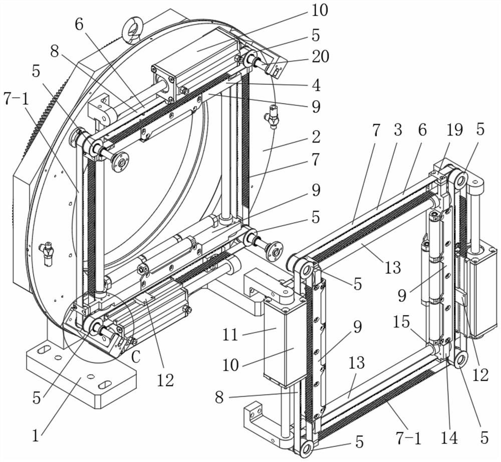
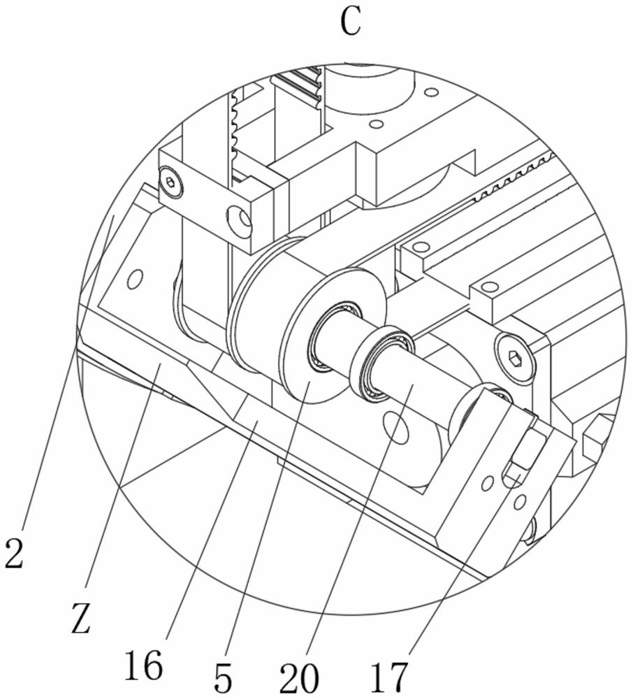
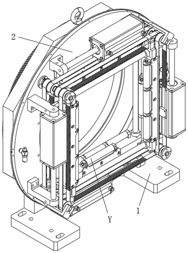
[0026] like Figure 1-6 , a four-jaw chuck for a laser pipe cutting machine in this embodiment includes a fixed seat 1, on which a turntable 2 is rotated, and the front side of the turntable 2 is respectively provided with horizontal and vertical clamping devices 3, 4, the horizontal and vertical clamping devices 3, 4 each include four runners 5 arranged at four corners, wherein any three pairs of adjacent runners 5 are driven by ring-shaped flexible members 6 Cooperate, wherein, the two flexible pieces 6 that are oppositely arranged are the first and second driven flexible pieces 7, 7-1 respectively, and the remaining flexible piece 6 is the active flexible piece 8, and the first driven flexible piece 6 is the active flexible piece 8. between the outer side of the flexible piece 7 and the inner side of the second driven flexible piece 7-1, and between the inner side of the first driven flexible piece 7 and the second driven flexible piece 7-1 The pressure roller assembly 9 i...

Embodiment 2

[0034] A working method of the four-jaw chuck described in Embodiment 1, comprising the following steps:

[0035] The driving device 10 drives the active flexible member 8 to move, and simultaneously drives the first and second driven flexible members 7 and 7-1 to move synchronously. The outer side and the inner side of the second driven flexible member 7-1 move in the same direction, and the inner side of the first driven flexible member 7 and the second driven flexible member 7-1 move in the same direction. The outer sides move in the same direction. Therefore, a pair of pressure roller assemblies 9 move in the opposite direction. When a pair of pressure roller assemblies 9 move in a straight line toward each other, the pipe material can be clamped, otherwise, the pipe material can be loosened. , a pair of pressing roller assemblies 9 of the lateral clamping device 3 is used for laterally clamping or loosening the pipe material, and a pair of pressing roller assemblies 9 of ...


PUM


Abstract

The invention relates to a four-jaw chuck for a laser pipe cutting machine. The four-jaw chuck comprises a fixed seat, a rotating disc is rotatably arranged on the fixed seat, a transverse clamping device and a longitudinal clamping device are respectively arranged on the front side of the rotating disc, each of the transverse clamping device and the longitudinal clamping device comprises four rotating wheels which are arranged at four corners, wherein any three pairs of adjacent rotating wheels are in transmission fit through annular flexible parts, the two flexible parts which are oppositely arranged are a first driven flexible part and a second driven flexible part respectively, the remaining flexible part is a driving flexible part, pressing roller assemblies are arranged between the outer side edge of the first driven flexible part and the inner side edge of the second driven flexible part and between the inner side edge of the first driven flexible part and the outer side edge of the second driven flexible part, the pressing roller assemblies of the transverse clamping device are longitudinally arranged, the pressing roller assemblies of the longitudinal clamping device are transversely arranged, and a driving device used for driving the driving flexible part to move is arranged on the rotating disc. The four-jaw chuck for the laser pipe cutting machine has the characteristics of large clamping jaw stroke, small size and low manufacturing cost.

Description

technical field [0001] The invention relates to the technical field of laser pipe cutting machines, in particular to a four-jaw chuck for a laser pipe cutting machine. Background technique [0002] The four-jaw chuck commonly used in the market for laser pipe cutting machines, including the connecting rod cylinder structure, is time-consuming and expensive to process, and has the following disadvantages: 1. The stroke size of the current chuck is mainly due to the direct push structure of the cylinder. The clamping range is 5-360mm, the claw stroke is small, and the opening in the middle of the traditional turntable is limited by the size of the cylinder, so it is difficult to open a large hole; 2. If you encounter a workpiece above 360mm, you need a larger stroke, which leads to The installation space in the diameter direction must also be large, so that the size and weight of the required chuck will be increased, making the overall size large and heavy. 3. Complex struc...

Claims


Application Information

Patent Timeline
Patent Type & Authority Applications(China)
IPC IPC(8): B23K26/70B23K26/38
CPCB23K26/702B23K26/38
Inventor 徐梅霞
Owner 领曼机械科技(常州)有限公司
Why Eureka
Try Eureka