
Metal cutting table based on metal corner distance measurement

A technology of metal cutting and corners, which is applied in metal processing, metal processing equipment, metal processing machinery parts, etc., can solve the problems of affecting the measured value, many cutting steps, and affecting the measurement accuracy, so as to reduce cutting steps and avoid errors Effect

Inactive Publication Date: 2021-11-05
赵雪峰
View PDF0 Cites 0 Cited by
  • Summary
  • Abstract
  • Description
  • Claims
  • Application Information

AI Technical Summary

Problems solved by technology

[0002] The method of metal cutting and fixing profiles is mostly to manually adjust the angle of the profiles. Precise metal cutting requires the use of precise measuring machinery for metal cutting. Most of the existing commonly used measuring devices are laser measuring devices. When the laser measuring device is used as a measuring device Accurate, no object obstruction between measurements, easy to use, before metal cutting, use laser distance measurement to plan the cutting route of the cutting machine, remove the laser, perform metal cutting, and perform multiple cuttings, and then perform laser measurement again , too many cutting steps
For arc cutting and laser cutting, the laser performs real-time distance measurement on the cutting position, and the light generated by it may affect the measurement value of the laser measuring device. The distance measurement of the cutting position will affect its measurement accuracy, and the flying debris generated by cutting may be Affect the measurement position of the laser, the laser position moves mechanically for a long time, and the reference position needs to be corrected regularly

Method used


Image

  • Metal cutting table based on metal corner distance measurement
  • Metal cutting table based on metal corner distance measurement
  • Metal cutting table based on metal corner distance measurement

Examples


Embodiment 1

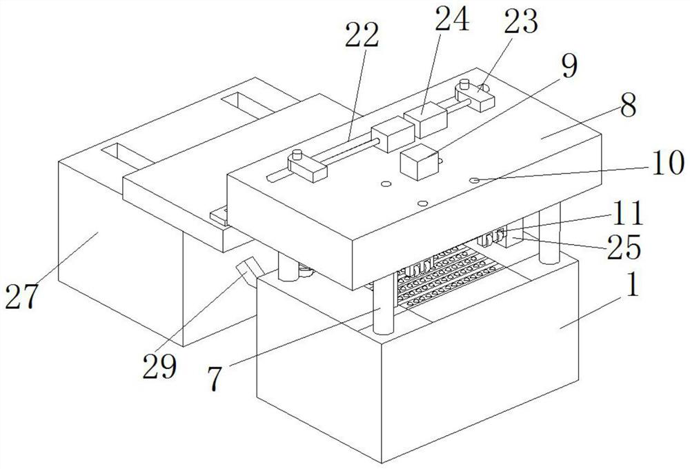
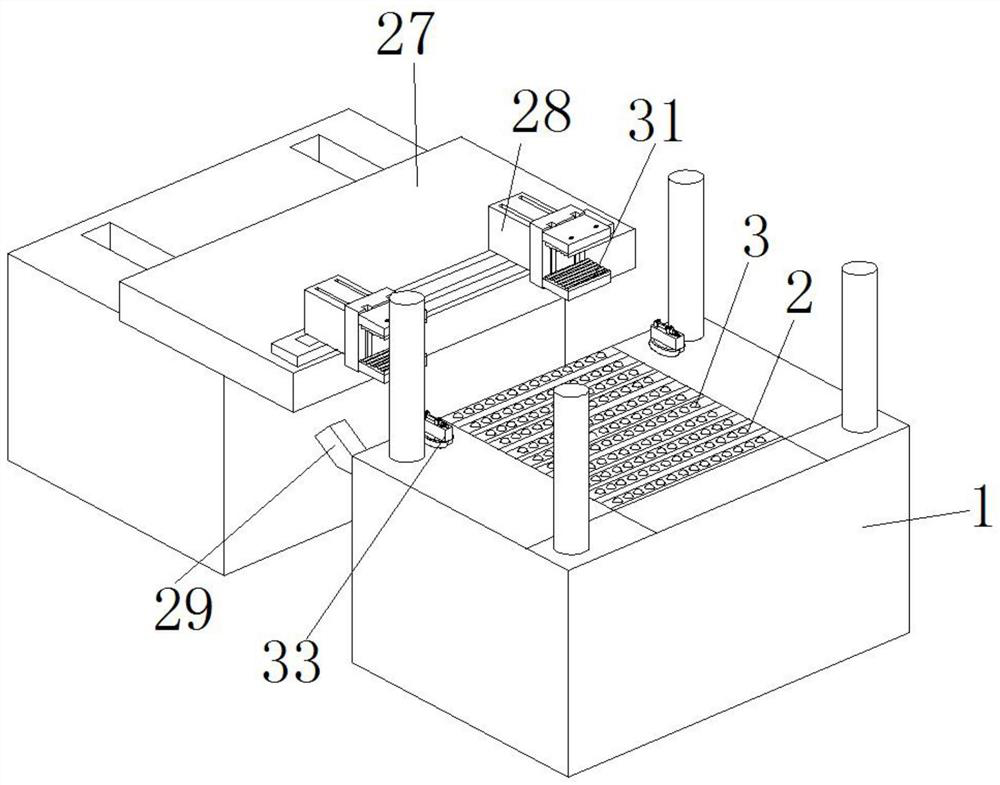
[0034] Such as Figure 1-10 As shown, a metal cutting table based on metal corner distance measurement includes an equipment base 1 .

[0035] By adopting the above technical scheme: the top of the equipment base 1 is provided with a spherical seat 2, and a spherical shaft 3 is movably installed in the spherical seat 2, and an electric micrometer 4 is installed at both ends of the equipment base 1. The base of the micrometer 4 and the distance measuring rod are all fixedly installed with a point laser mount 5, the top of the point laser mount 5 is fixedly mounted with a point laser 6, and the top of the equipment base 1 is fixedly mounted with a mounting platform 8 through a support rod 7 , a hydraulic device 9 is installed on the installation platform 8, a point laser device 29 is arranged on the equipment base 1, a wired laser device is arranged below the installation platform 8, and the electric micrometer 4 is installed through an angle measuring instrument refitting platf...

Embodiment 2

[0042] Such as Figure 1-10 As shown, a metal cutting table based on metal corner distance measurement, including.

[0043] By adopting the above-mentioned technical scheme: a guide rail bar 10 is arranged beside the hydraulic device 9, and the guide rail bar 10 is connected with a pressing device 11, and the pressing device 11 includes a fixed plate 12, and the fixed plate 12 is fixedly installed on the On the frame 13, the four corners of the bottom of the mounting frame 13 are provided with pressure roller mounts 14, and the bottom corners of the bottom of the pressure roller mounts 14 are all provided with pressure roller mounting bearings, and the pressure roller mounting bearings are movable to install pressure rollers. wheel 15, the pressing wheel 15 is connected with the first transmission shaft 16, the first transmission shaft 16 is connected with the second transmission shaft 17, and the second transmission shaft 17 is connected with the third transmission shaft 18 ...


PUM


Abstract

The invention discloses a metal cutting table based on metal corner distance measurement, the metal cutting table comprises an equipment base, a spherical seat is arranged at the top of the equipment base, a spherical shaft is movably mounted in the spherical seat, and electric micrometers are mounted at two ends of the equipment base. Bases of the electric micrometers and a distance measuring rod are fixedly provided with point laser mounting seats, the top of each point laser mounting seat is fixedly provided with a point laser, a mounting table is fixedly mounted above the equipment base through a supporting rod, a hydraulic device is mounted on the mounting table, and a guide rail rod is arranged beside the hydraulic device. Compared with the prior art, the metal cutting table has the following beneficial effects that a laser device is arranged to measure other positions of a profile to obtain the position change of the profile, the position of the profile can be adjusted at any time in the cutting process, the position change of the profile is monitored in real time, the situation that a reference value is changed due to repeated mechanical movement of the laser device is avoided, cutting steps are reduced, and errors are avoided.

Description

technical field [0001] The invention relates to the field of metal cutting, in particular to a metal cutting table based on metal corner distance measurement. Background technique [0002] The method of metal cutting and fixing profiles is mostly to manually adjust the angle of the profiles. Precise metal cutting requires the use of precise measuring machinery for metal cutting. Most of the existing commonly used measuring devices are laser measuring devices. When the laser measuring device is used as a measuring device Accurate, no object obstruction between measurements, easy to use, before metal cutting, use laser distance measurement to plan the cutting route of the cutting machine, remove the laser, perform metal cutting, and perform multiple cuttings, and then perform laser measurement again , too many cutting steps. For arc cutting and laser cutting, the laser performs real-time distance measurement on the cutting position, and the light generated by it may affect th...

Claims


Application Information

Patent Timeline
Patent Type & Authority Applications(China)
IPC IPC(8): B23Q17/22B23Q17/24B23K9/013B23K26/38B23Q7/04B23Q7/06
CPCB23Q17/2291B23Q17/2419B23Q17/2471B23Q7/06B23Q7/046B23K26/38B23K9/013
Inventor 不公告发明人
Owner 赵雪峰
Learn More