Electric automobile electro-hydraulic composite braking system based on hub motor driving and front and rear axle braking force distribution method

A braking force distribution, electro-hydraulic compound technology, applied in electric braking system, electric vehicle charging technology, electric vehicle, etc., can solve the problem that the rear axle braking force distribution line β″ may appear above the original vehicle β line and lose steering. ability, little consideration, etc., to achieve the effects of reasonable and feasible control methods, reducing the tendency to lock first, strong typicality and generality

Inactive Publication Date: 2021-11-05
JIUJIANG VOCATIONAL & TECHN COLLEGE
View PDF0 Cites 1 Cited by
  • Summary
  • Abstract
  • Description
  • Claims
  • Application Information

AI Technical Summary

Problems solved by technology

[0004] However, in the existing research on the electro-hydraulic hybrid braking system of electric vehicles driven by in-wheel motors, the main research is how to reasonably distribute the proportion of electro-hydraulic braking force and improve the regenerative braking energy of the motor under a certain braking intensity. Recycling utilization rate, but little consideration is given to how the front and rear wheel braking force distribution curve is distributed and the impact on vehicle stability after the electric vehicle adopts electro-hydraulic hybrid braking
However, in the actual braking conditions of the combined braking of electric vehicles, the distribution of electro-hydraulic braking force has a great influence on the stability of the vehicle. On the one hand, when the front wheels adopt electro-hydraulic braking, the The power distribution line β′ will shift to the right relative to the β line of the original car, which will increase the tendency of the front wheel lock, and the front wheel lock will cause the loss of steering ability. On the other hand, when the four wheels adopt electro-hydraulic brake, The brake force distribution line β″ of the front and rear axles of the car may appear above the β line of the original car, which may cause very dangerous tail flick and sideslip, which is not allowed
At present, electric vehicles driven by in-wheel motors use electro-hydraulic brakes, and the reports on the distribution curves of the front and rear wheel braking forces have not been made public. value and practical significance

Method used


Image

  • Electric automobile electro-hydraulic composite braking system based on hub motor driving and front and rear axle braking force distribution method
  • Electric automobile electro-hydraulic composite braking system based on hub motor driving and front and rear axle braking force distribution method
  • Electric automobile electro-hydraulic composite braking system based on hub motor driving and front and rear axle braking force distribution method

Examples


Embodiment 1

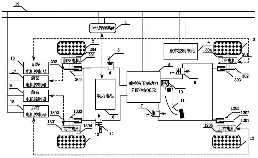
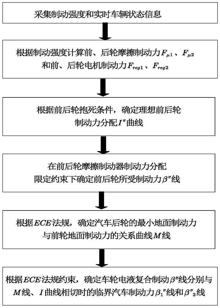
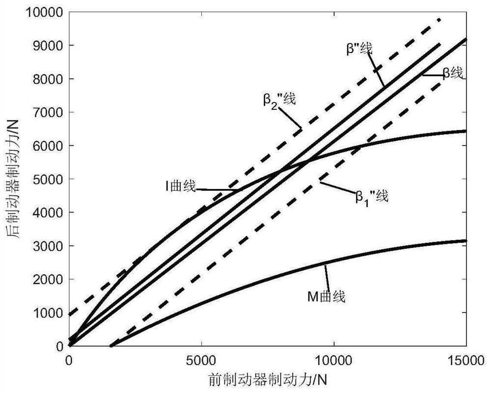
[0094] like figure 1 As shown, the present invention discloses a four-wheel electro-hydraulic composite braking system for electric vehicles driven by in-wheel motors, including a hydraulic friction braking module, a motor regenerative braking module, an energy management module and a vehicle control module; The friction braking module includes a vehicle control unit 4, a brake pedal 11, a wire-controlled hydraulic braking force distribution control unit 8, a front left solenoid valve 5, a rear left solenoid valve 9, a rear right solenoid valve 7, a front right solenoid valve 14 and Brake pedal displacement sensor 10, etc.; the vehicle control unit 4 is electrically connected to the CAN line 19, receives signals from the brake pedal displacement sensor 10, speed sensors 204, 304, 1204, and 1304, and judges the state of the vehicle in real time through analysis and synthesis , determine the required braking force, and then distribute the regenerative braking force of the motor ...

Embodiment 2

[0132] The invention discloses an electric vehicle front wheel electro-hydraulic composite braking system driven by a hub motor, which specifically includes: 1. a battery management system; 2. the front left wheel, 201, the front left hub motor, 202, the front left brake Disk, 203, front left axle, 204, front left motor speed sensor; 3, rear left wheel; 4, vehicle control unit; 5, front left solenoid valve; 6, power battery; 7, rear right solenoid valve; 8, 9. Rear left solenoid valve; 10. Brake pedal displacement sensor; 11. Brake pedal; 12. Rear right wheel; 13. Front right wheel, 1301. Front right hub motor, 1302 1303, front right axle, 1304, front right motor speed sensor; 14, front right solenoid valve; 15, front right motor controller; 16, front left motor controller; 17, CAN line. The difference from Example 1 is that the electro-hydraulic brake system described in this embodiment adopts the electro-hydraulic brake system for the front wheels, such as Figure 4 shown. ...


PUM


Abstract

The invention provides an electric automobile electro-hydraulic composite braking system based on hub motor driving and a front and rear axle braking force distribution method. The electric automobile electro-hydraulic composite braking system comprises a hydraulic friction braking module, a motor regenerative braking module, an energy management module and a whole automobile control module. The hydraulic friction braking module comprises a whole automobile control unit, a drive-by-wire hydraulic braking force distribution control unit, an electromagnetic valve and the like; the motor regenerative braking module comprises a hub motor, a motor controller and a rotating speed sensor; and the energy management module comprises a battery management system and a power battery. In the braking process of the automobile, a sensor detects the required braking strength of the automobile and the state information of the automobile, and the whole automobile control unit distributes the electro-hydraulic composite braking force through the hydraulic friction braking module and the motor regenerative braking module. Meanwhile, the invention provides an electro-hydraulic composite braking front and rear axle braking force distribution method, safety areas of front and rear axle braking force distribution beta' and beta'' lines are given, the tendency that rear wheels of the automobile are locked first is reduced, and the braking safety of the automobile is improved.

Description

technical field [0001] The invention relates to the technical field of electro-hydraulic composite braking of electric vehicles, in particular to an electro-hydraulic composite braking system of electric vehicles driven by hub motors and a method for distributing braking force between front and rear axles. Background technique [0002] With the development of automobile technology, "intelligence, networking, and electrification" is the development direction of future automobiles. The brake-by-wire system is the key technology for realizing automobile intelligence. Electro-hydraulic brake (EHB) is the One form, which can achieve decoupling from the brake pedal, has attracted great attention from scholars at home and abroad. The electric vehicle driven by the in-wheel motor has the advantages of compact structure, high transmission efficiency, and is conducive to making full use of the ground adhesion. It is integrated with the electro-hydraulic braking system to form an elect...

Claims


Application Information

Patent Timeline
Patent Type & Authority Applications(China)
IPC IPC(8): B60L7/10B60L7/24B60R16/023
CPCB60L7/10B60L7/24B60R16/0231B60L2220/44Y02T90/167Y04S30/12
Inventor 张瑞军章雯
Owner JIUJIANG VOCATIONAL & TECHN COLLEGE
Why Eureka
Try Eureka