Textile fabric conveying and winding machine

A technology of textile fabrics and machinery, which is applied in the field of textile fabric conveying and winding machinery, which can solve the problems of fabric wrinkles, poor fabric rolling effect, and easy wrinkles and offsets of fabrics, so as to avoid wrinkles, ensure the smoothness of fabrics, and ensure the collection The effect of the volume effect

Active Publication Date: 2021-11-05
徐州市佳宁纺织科技有限公司
View PDF7 Cites 3 Cited by
  • Summary
  • Abstract
  • Description
  • Claims
  • Application Information

AI Technical Summary

Problems solved by technology

[0003] The above-mentioned rewinding device and other rewinding devices in the prior art have the following problems when rewinding the cloth: (1) before winding, the end of the cloth needs to be fixed on the winding roller by pasting, etc. Finally, in the process of removing the cloth from the winding roller, the innermost layer of cloth attached to the winding roller is prone to wrinkles and offsets, resulting in poor winding effect of the cloth; (2) the cloth in the winding process There will be friction between them, and the friction will make the fabric wrinkle, which will affect the winding effect of the fabric

Method used


Image

  • Textile fabric conveying and winding machine
  • Textile fabric conveying and winding machine
  • Textile fabric conveying and winding machine

Examples


Embodiment Construction

[0026] The embodiments of the present invention will be described in detail below with reference to the accompanying drawings, but the present invention can be implemented in many different ways defined and covered by the claims.

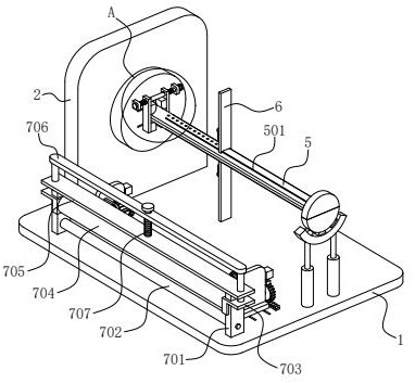
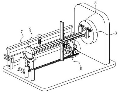
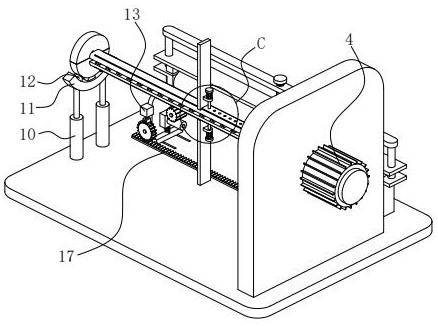
[0027] like Figure 1 to Figure 3As shown, this embodiment provides a textile fabric conveying and winding machine, including a horizontal bottom plate 1, a vertical plate 2 is fixedly installed on the bottom plate 1, and a vertical disk 3 is rotatably installed on the surface of the vertical plate 2. A horizontal drive motor 4 is fixedly installed on the straight plate 2 through the motor seat, and the output shaft of the drive motor 4 is fixedly connected with the disc 3; The bar-shaped splint 5, the bar-shaped splint 5 is perpendicular to the disc 3 and is slidably matched with the disc 3 along the radial direction of the disc 3; A strip baffle 6 perpendicular to the strip splint 5 is slidably installed on the upper part through the strip groove...


PUM


Abstract

The invention belongs to the technical field of textile, and particularly relates to a textile fabric conveying and winding machine which comprises a bottom plate. A vertical plate is mounted on the bottom plate; a disc is rotatably mounted on the surface of the vertical plate; a driving motor is fixedly mounted on the vertical plate; two strip-shaped clamping plates are mounted on the surface of the disc; strip-shaped grooves are formed in the strip-shaped clamping plates in the length directions of the strip-shaped clamping plates; strip-shaped baffles perpendicular to the strip-shaped clamping plates are slidably mounted on the strip-shaped clamping plates through the strip-shaped grooves; and a pressing mechanism is mounted on the bottom plate. According to the textile fabric conveying and winding machine provided by the invention, in the process of taking down cloth, adhesion force does not exist between the cloth on the innermost layer and the strip-shaped clamping plates, and the friction force between the cloth on the innermost layer and the strip-shaped clamping plates is reduced through rolling wheels on the strip-shaped clamping plates, so that the cloth on the innermost layer does not wrinkle or deviate, and the rolling effect of the cloth is guaranteed; the cloth is pressed through the pressing mechanism, so that the cloth is in a tensioned state; and the edges of the two sides of the cloth are reversely flattened through a flattening roller, so that the cloth is ensured to be flat.

Description

technical field [0001] The invention belongs to the technical field of textiles, and in particular relates to a textile cloth conveying and winding machine. Background technique [0002] Textile fabrics are often made of low-elastic polyester yarns or special-shaped polyester yarns, nylon yarns, cotton yarns, wool yarns, etc. etc., are woven on the textile machine; after the textile cloth is formed, in order to facilitate storage and transportation, it usually needs to be rolled. Installed on the installation panel, the fabric winding assembly is installed on the installation panel, and the installation panel is provided with a dust removal installation slot; the dust removal assembly includes a dust removal drive part, an output shaft, a fan blade and a fan cover, and the dust removal drive part is driven and connected to the output shaft. The fan blade is arranged on the output shaft, the winding driving part is arranged on the first supporting column, the winding driving...

Claims


Application Information

Patent Timeline
Patent Type & Authority Applications(China)
IPC IPC(8): B65H75/28B65H23/26
CPCB65H75/285B65H23/26B65H2301/51256B65H2701/174
Inventor 祁峰
Owner 徐州市佳宁纺织科技有限公司
Why Eureka
Try Eureka