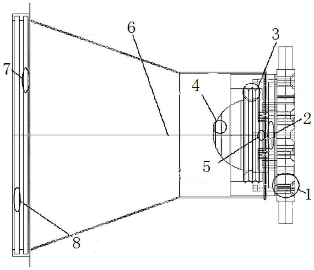
Transmission-type light distribution method for aircraft landing lamp

An aircraft landing light and transmissive technology, which is applied in the field of transmissive light distribution of aircraft landing lights, can solve the problems of low light utilization rate, large volume and weight, uneven light spot, etc., so as to improve illumination brightness and intensity, and light utilization rate. High, avoid the effect of excessive temperature

Pending Publication Date: 2021-11-05
SHAANXI CHANG LING SPECIAL EQUIP
View PDF0 Cites 0 Cited by
  • Summary
  • Abstract
  • Description
  • Claims
  • Application Information

AI Technical Summary

Problems solved by technology

[0008] The purpose of the present invention is to provide a transmissive light distribution method for aircraft landing lights, which has the advantages of high light utilization rate and light use, and solves the low light utilization rate and volume weight caused by the existing reflective light distribution method. The problem of large and uneven light spots

Method used


Image

  • Transmission-type light distribution method for aircraft landing lamp

Examples


Embodiment Construction

[0024] The following will clearly and completely describe the technical solutions in the embodiments of the present invention with reference to the accompanying drawings in the embodiments of the present invention. Obviously, the described embodiments are only some, not all, embodiments of the present invention. Based on the embodiments of the present invention, all other embodiments obtained by persons of ordinary skill in the art without making creative efforts belong to the protection scope of the present invention.

[0025] In the description of the invention, it should be noted that the terms "upper", "lower", "inner", "outer", "front end", "rear end", "both ends", "one end", "another end" etc. The indicated orientation or positional relationship is based on the orientation or positional relationship shown in the drawings, and is only for the convenience of describing the present invention and simplifying the description, rather than indicating or implying that the referre...


PUM


Abstract

The invention discloses a transmission-type light distribution method for an aircraft landing lamp, which comprises a radiator base, the left side of the radiator base is fixedly connected with an LED and substrate, the left side of the LED and substrate is movably connected with a primary lens, the outer side of the LED and substrate is sleeved with a second-level lens pressing ring, the surface of the second-level lens pressing ring is movably connected with a second-level lens body, the surface of the second-level lens pressing ring is sleeved with a light shield, the right side of the light shield is fixedly connected with the connecting position of the radiator base, and the left side of an inner cavity of the light shield is movably connected with a third-level lens. Through the radiator base, the LED, the substrate, the second-level lens pressing ring, the second-level lens body, the primary lens, the light shield, the third-level lens and the protective glass, the landing lamp has the advantages of being high in light ray utilization rate and convenient to use, and the problems of low light ray utilization rate, large size and weight and uneven light spots caused by an existing reflection type light distribution method are solved.

Description

technical field [0001] The invention relates to the technical field of aircraft landing lights, in particular to a transmissive light distribution method for aircraft landing lights. Background technique [0002] The existing landing lights all adopt reflective cup light distribution, that is, the landing light source is composed of a group of independent lamp beads arranged in a certain form, and each lamp bead has an independent reflective cup, that is, the reflective light distribution method is used to achieve landing The lamp head light source and reflector cup type light distribution scheme are relatively simple and easy to implement, but they have the following defects: [0003] The utilization rate of the outgoing light is low: the deepest reflector is about 60%. As an airborne light source, the power of the landing light is strictly limited. The low utilization rate will lead to insufficient light intensity of the light source and severe heat generation. In other w...

Claims


Application Information

Patent Timeline
IPC IPC(8): F21S2/00F21V5/04F21V1/00F21V29/70F21V17/00F21Y115/10F21W111/04
CPCF21S2/00F21V5/04F21V1/00F21V29/70F21V17/00F21Y2115/10F21W2111/04
Inventor 郗飞倪珍刘义芳其他发明人请求不公开姓名
Owner SHAANXI CHANG LING SPECIAL EQUIP
Why Eureka
Try Eureka