Synthetic resin stent

A synthetic resin and network-forming technology, which can be used in stents, medical science, prostheses, etc., and can solve problems such as inability to perform and poor followability

Pending Publication Date: 2021-11-05
JMS CO LTD
View PDF1 Cites 2 Cited by
  • Summary
  • Abstract
  • Description
  • Claims
  • Application Information

AI Technical Summary

Problems solved by technology

[0003] Since synthetic resin stents are inferior to metal stents in terms of self-expandability, restoration, adhesion to digestive tracts such as the intestinal tract, and followability to peristaltic movements of digestive tracts, synthetic resin stents are produced in the same shape as metal stents. In the case of a resin bracket, the required performance may not be exhibited

Method used


Image

  • Synthetic resin stent
  • Synthetic resin stent
  • Synthetic resin stent

Examples


no. 1 approach

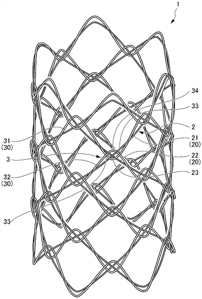
[0031] refer to figure 1 and figure 2 , the biodegradable stent 1 of the first embodiment will be described.

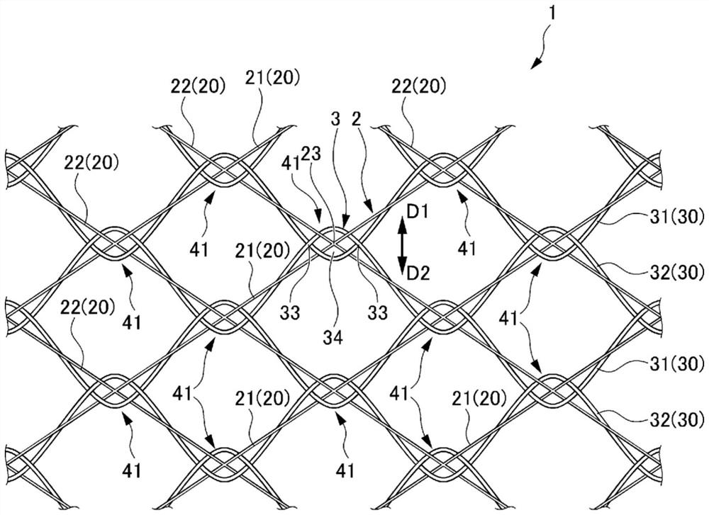
[0032] figure 1 It is a perspective view showing the biodegradable stent 1 according to the first embodiment of the present invention. figure 2 yes figure 1 An enlarged view of the biodegradable scaffold 1 shown.

[0033] The synthetic resin stent of this embodiment is a biodegradable stent 1 made of biodegradable fibers, such as figure 1 and figure 2 As shown, the mesh-shaped cylindrical portion 2 (first knitting configuration portion) and the wave-shaped knitting portion 3 (second knitting configuration portion) knitted and arranged on the mesh-shaped cylindrical portion 2 are provided.

[0034] The mesh-shaped cylindrical part 2 is formed into a cylindrical shape by weaving a plurality of fibers 20 into a mesh shape, and has a plurality of rhombic holes formed by the fibers 20 and arranged in an orderly manner on the outer periphery. The mesh of the mesh-...

no. 2 approach

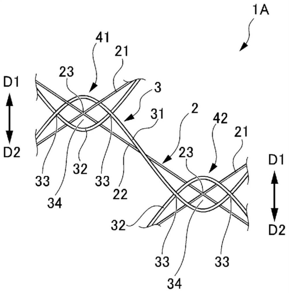
[0066] The biodegradable stent 1A of the second embodiment will be described below. image 3 It is a figure which shows the biodegradable stent 1A of 2nd Embodiment.

[0067] Such as image 3 As shown, the biodegradable stent 1A of the second embodiment has a first hook portion 41 ( image 3 in the left side) and the second hook part 42 ( image 3 in the right side) to form. The plurality of first hook portions 41 and the plurality of second hook portions 42 of the biodegradable stent 1A are arranged alternately in a helical shape in the circumferential direction.

[0068] because image 3 The structure of the illustrated first hooking portion 41 is the same as that of the first hooking portion 41 described in the first embodiment, so description thereof will be omitted.

[0069] The structure of the second hook portion 42 will be described below.

[0070] Such as image 3 As shown, at the second hooking portion 42, like the first hooking portion 41 of the first embodim...

no. 3 approach

[0080] The biodegradable stent 1B of the third embodiment will be described below. Figure 4 It is a figure which shows the biodegradable stent 1B of 3rd Embodiment.

[0081] In the biodegradable stent 1B of the third embodiment, compared with the biodegradable stent 1 of the first embodiment, the wave-shaped braided portion 3 (the first braided portion) woven into the mesh-shaped tubular portion 2 (the first braided portion) is In the second braided structure part), for the rows in which the plurality of first hooking parts 41 are arranged in a row in the circumferential direction, they are not arranged next to each other in the axial direction of the biodegradable stent 1A, but separated by a certain interval. and configured separately.

[0082] Such as Figure 4 As shown, the wave-shaped braided portion 3 has a plurality of first hooking portions 41 in the axial direction of the mesh-shaped tubular portion 2 having a plurality of first intersection points 23, and has a ro...


PUM

PropertyMeasurementUnit
diameteraaaaaaaaaa
diameteraaaaaaaaaa
diameteraaaaaaaaaa

Abstract

Provided is a stent which can ensure the storability in thin tubular members such as delivery systems and which is insusceptible to positional displacement after placement of the stent in an affected part of a bodily conduit. The synthetic resin stent 1 comprises a tubular first braid component 2 comprising a plurality of fibers that are braided into a net-like form, and a second braid component 3 comprising a plurality of fibers that are disposed braided into the first braid component 2 to form an annular shape. The first braid component 2 includes a plurality of first fibers 21, a plurality of second fibers 22, and a plurality of first intersections 23, and the second braid component 3 includes a plurality of wave-like third fibers 31 disposed separated in an axial direction and a plurality of wave-like fourth fibers 32 disposed separated in the axial direction. At least one of the first intersections 23 is disposed in an intersection region 34 surrounded by the third fiber 31 and the fourth fiber 32.

Description

technical field [0001] The present invention relates to synthetic resin scaffolds such as biodegradable scaffolds. Background technique [0002] Conventionally, for stenotic diseases (tumor, inflammation, etc.) of living ducts such as blood vessels and digestive tracts, a stent is placed in the stenosis to dilate the stenosis. As the holder, for example, metal and synthetic resin holders are known. Among them, a metal stent requires a surgical operation when it is pulled out from the body, and thus imposes a great burden on the patient. Therefore, the use of metal stents is limited to cases such as malignant tumors where semi-permanent placement or surgery is planned. From such a background, biodegradable stents as synthetic resin stents have been proposed as stents for cases where metal stents cannot be used (see, for example, Patent Document 1). [0003] Since synthetic resin stents are inferior to metal stents in terms of self-expandability, restoration, adhesion to di...

Claims


Application Information

Patent Timeline
Patent Type & Authority Applications(China)
IPC IPC(8): A61F2/852A61F2/90
CPCA61F2/90A61F2210/0004A61F2210/0076A61F2/915
Inventor 山本彩佳福泷修司
Owner JMS CO LTD
Why Eureka
Try Eureka