Distal tibiofibular joint screw guide forceps

A technology for guiding pliers and joints, which is applied in the field of medical appliances and can solve problems such as inability to judge nails well

Inactive Publication Date: 2021-11-09
THE FIRST PEOPLES HOSPITAL OF CHANGZHOU
View PDF0 Cites 0 Cited by
  • Summary
  • Abstract
  • Description
  • Claims
  • Application Information

AI Technical Summary

Problems solved by technology

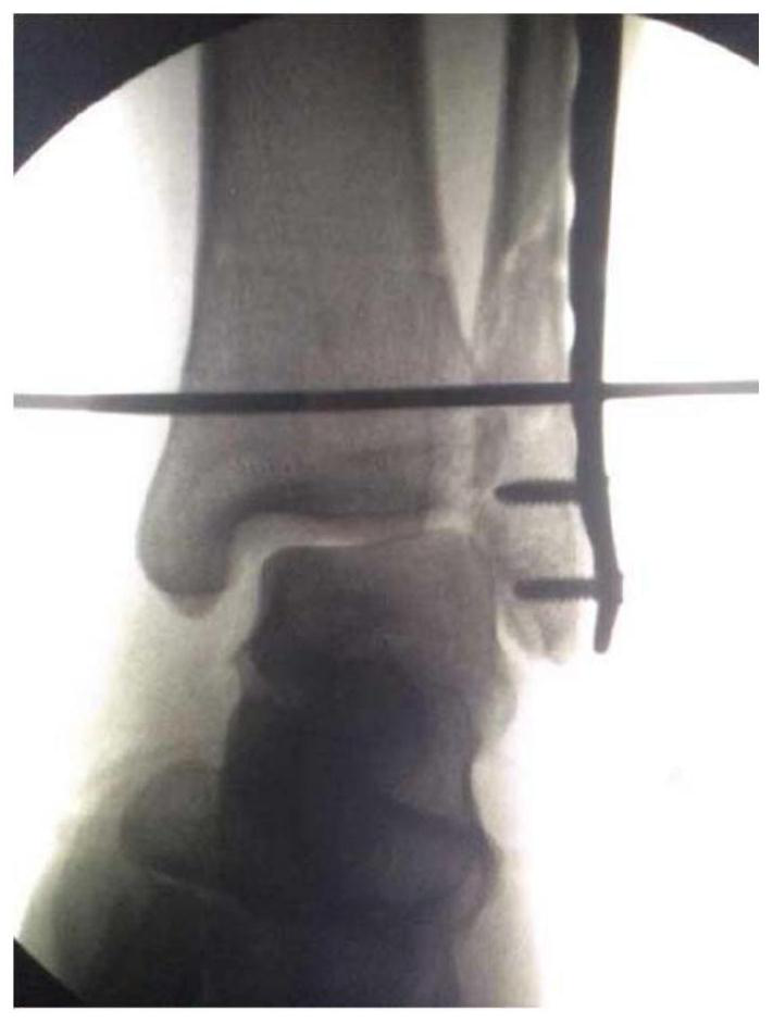
Moreover, intraoperative X-ray fluoroscopy has overlapping effects, such as image 3 , and it is not very good to judge whether the nail is hit in the middle of the articular surface, which is the strongest biomechanics

Method used


Image

  • Distal tibiofibular joint screw guide forceps
  • Distal tibiofibular joint screw guide forceps
  • Distal tibiofibular joint screw guide forceps

Examples


Embodiment 1

[0037] Such as Figure 4 , Figure 5 and Figure 6 As shown, the present invention provides a lower tibiofibular joint screw-guided forceps, comprising a handle 1 and a handle 2, the junction of the handle 1 and the handle 2 is connected by a rivet 3 in rotation, the One end of the pliers handle 1 and the pliers handle 2 are respectively integrally formed with a pliers mouth 11 and a pliers mouth 2 21, and the pliers mouth 1 1 and the pliers mouth 2 21 are both arranged to be curved inwardly;

[0038] The other end of the pliers handle 2 is welded with an arc-shaped plate 4, and the bottom of the arc-shaped plate 4 is provided with an arc-shaped clamping mechanism 42, and the arc-shaped clamping mechanism 42 includes an inner arc-shaped plate 421, a connecting plate 422 , the outer arc-shaped plate 423, the inner arc-shaped plate 421 is welded on the inside of the arc-shaped plate 4, and the handle-1 is located between the inner arc-shaped plate 421 and the outer arc-shaped ...

Embodiment 2

[0046] Roughly the same as Example 1, the differences are as follows:

[0047] Such as Figure 7-Figure 11 As shown, the outer sliding sleeve of the arc-shaped plate 4 and the inner arc-shaped plate 421 is provided with a sleeve 5, the outer wall of the sleeve 5 is welded with a round tube 6, and the inner end of the round tube 6 is facing the For the rivet 3, a threaded rod 51 is installed on the top of the sleeve 5, and the sleeve 5 is loosened and positioned by tightening the threaded rod 51.

[0048] By adopting the above-mentioned technical scheme, clamp the two points on the rear side of the tibia and fibula through the handle one 1 and the mouth one 11, clamp the two points on the front side of the tibia and fibula through the handle one 1 and the two points on the front side of the fibula through the handle one 1 Together with the forceps handle 2 and forceps mouth one 11 and forceps mouth two 21, it clamps the shin and fibula at four points in front and back contact ...


PUM


Abstract

The invention discloses distal tibiofibular joint screw guide forceps. The distal tibiofibular joint screw guide forceps comprise a first forceps handle and a forceps handle, the joint of the first forceps handle and the forceps handle is rotationally connected through a rivet, a first forceps mouth and a second forceps mouth are integrally formed at one end of the first forceps handle and one end of the forceps handle respectively, and the first forceps mouth and the second forceps mouth are both arranged in an arc-shaped bending mode towards the inner side; and an arc-shaped plate is welded to the other ends of the forceps handle, an arc-shaped clamping plate mechanism is arranged at the bottom of the arc-shaped plate and comprises an inner arc-shaped plate, a connecting plate and an outer arc-shaped plate, the inner arc-shaped plate is welded to the interior of the arc-shaped plate, the first forceps handle is located between the inner arc-shaped plate and the outer arc-shaped plate, a first angle scribed line is engraved on the top of the arc-shaped plate, a through hole is formed in a base body of the arc-shaped plate, and the circle center of the arc-shaped plate is located on the center line of the rivet. According to the scheme, the distal tibiofibular joint screw guide forceps are used as a guider when a distal tibiofibular joint is subjected to a fixing operation, and a nail can be conveniently hit in the middle of a distal tibiofibular joint surface, namely the strongest biomechanics position.

Description

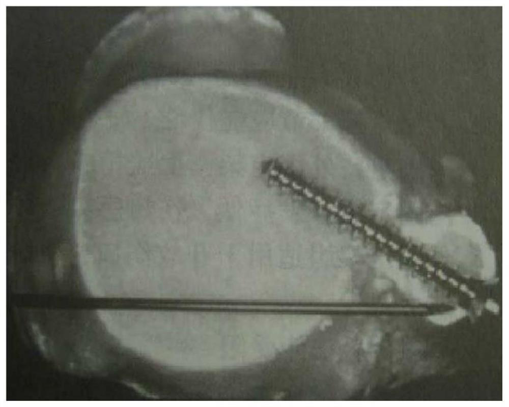
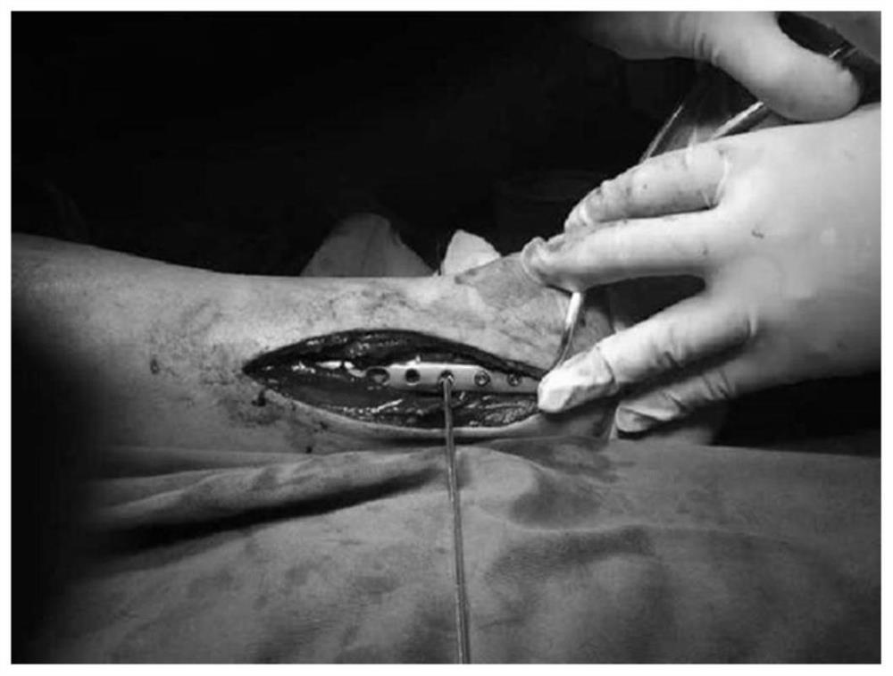
technical field [0001] The invention belongs to the technical field of medical appliances, in particular to a guiding forceps for inferior tibiofibular joint screws. Background technique [0002] The inferior tibiofibular ligament is a very important stability structure of the ankle joint. The reason for many surgical failures is that the inferior tibiofibular ligament is not fixed, or the fixation is invalid. The traditional method: perpendicular to the inferior tibiofibular joint, and tilted 25-30 degrees from the back to the front degree, such as figure 1 As shown, the picture you see is an anatomical cross-sectional view of the cadaver specimen. This cross-sectional plane cannot be observed during the operation, and the position of the screw cannot be judged. Under direct vision during the operation, only the outer side of the fibula can be seen, such as figure 2 , It is impossible to judge the midpoint of the arc of the articular surface, so that the nail is inserted...

Claims


Application Information

Patent Timeline
Patent Type & Authority Applications(China)
IPC IPC(8): A61B17/90A61B17/28A61B17/17
CPCA61B17/88A61B17/282A61B17/2841A61B17/1775
Inventor 朱鼎
Owner THE FIRST PEOPLES HOSPITAL OF CHANGZHOU
Why Eureka
Try Eureka