
Magnetically-driven rotary atomizer

A rotary atomizer, magnetic drive technology, applied in the direction of spray evaporation, evaporator accessories, liquid droplet granulation, etc., can solve the problems of high motor power, large atomizer volume, shortened atomizer life, etc. Achieve the effect of reducing frictional resistance, ensuring the sealing effect, and simplifying the installation and disassembly process

Pending Publication Date: 2021-11-09
JIANGSU JINGYUAN ENVIRONMENTAL PROTECTION
View PDF8 Cites 0 Cited by
  • Summary
  • Abstract
  • Description
  • Claims
  • Application Information

AI Technical Summary

Problems solved by technology

Its disadvantages are: in the drying field, the working temperature of the atomizer is generally high, the ambient temperature often reaches above 300°C, and the working temperature near the atomizer is also above 150°C. The ordinary motor and shafting structure cannot operate at this temperature. Long-term operation under low conditions will shorten the life of the atomizer and increase the failure rate
At present, the atomizer is generally composed of a motor, a speed increase box, a cooling and lubrication system, and an atomizing disc; such an atomizer is generally large in size and heavy in weight, which is not conducive to installation and daily cleaning and maintenance.
The structure of the traditional gearbox and shaft system requires high motor power and relatively low energy conversion

Method used


Image

  • Magnetically-driven rotary atomizer

Examples


Embodiment Construction

[0021] Embodiments of the present invention are described in detail below, examples of which are shown in the drawings, wherein the same or similar reference numerals designate the same or similar elements or elements having the same or similar functions throughout. The embodiments described below by referring to the figures are exemplary and are intended to explain the present invention and should not be construed as limiting the present invention.

[0022] In describing the present invention, it is to be understood that the terms "upper", "lower", "front", "rear", "left", "right", "top", "bottom", "inner", "outer" ” and other indicated orientations or positional relationships are based on the orientations or positional relationships shown in the accompanying drawings, which are only for the convenience of describing the present invention and simplifying the description, rather than indicating or implying that the referred device or element must have a specific orientation, wi...


PUM


Abstract

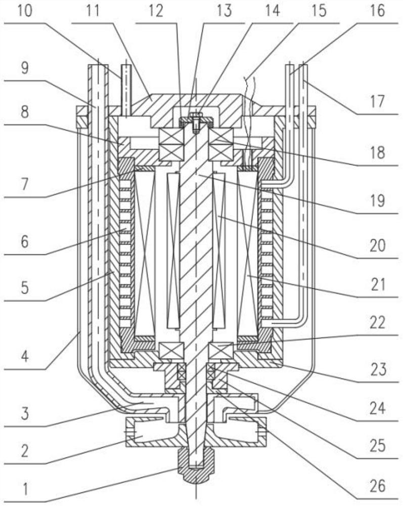
The invention relates to a magnetically-driven rotary atomizer. An atomizer shell is connected with an atomizer inner container in a welded mode. An atomizer cover plate is connected with an upper bearing. A feeding device is arranged on the left side of the atomizer shell and the left side of the atomizer inner container, and the feeding device is provided with a feeding opening. A feed liquid distribution disc is arranged at the portion, at the bottom of the atomizer shell, of the feeding device. A feed liquid outlet is formed in the rear side of the feed liquid distribution disc. A main shaft containing space is arranged below the atomizer cover plate, a main shaft is arranged in the main shaft containing space and is a tapered main shaft, and a shaft end cover is fixed to the top of the main shaft through a locking bolt. A plurality of upper bearings are arranged below a connecting end. The upper bearings are connected with the main shaft and the shaft end cover through locking rings. A plurality of magnetic force receiving devices are symmetrically arranged on the periphery of the main shaft, a plurality of magnetic force generating devices are symmetrically arranged outside the magnetic force receiving devices, and the outer portions and the bottoms of the magnetic force generating devices are fixedly connected with a cooling jacket. The cooling jacket is detachably connected with the atomizer inner container.

Description

technical field [0001] The invention relates to the technical field of evaporation and drying, in particular to a magnetically driven rotary atomizer. Background technique [0002] Evaporation and drying of liquids by means of rotary atomization evaporation is a common drying and granulation method. The main method of rotary atomization is that when the liquid is sent to the high-speed rotating atomizing disc, due to the action of centrifugal force, the liquid is stretched into a thin film or drawn into filaments (depending on the rotational speed and the amount of slurry), and breaks at the edge of the atomizing disc Disperses into droplets. The size of the droplets depends on the rotation speed and the amount of liquid handled. The atomizer can ensure that the particle size distribution of the atomized droplets does not change significantly when the liquid flow rate does not change greatly. The atomized liquid is fully and uniformly mixed with the high-temperature gas, ...

Claims


Application Information

Patent Timeline
Patent Type & Authority Applications(China)
IPC IPC(8): B01D1/20B01D1/30B01J2/04
CPCB01D1/20B01D1/30B01J2/04
Inventor 季献华李武林仲明姜勇姚志全李宽徐俊秀王辰秦小波
Owner JIANGSU JINGYUAN ENVIRONMENTAL PROTECTION
Learn More