
Guide arm automatic grinding system and automatic grinding method

A guide arm, automatic technology, applied in the direction of grinding automatic control device, grinding machine, grinding feed motion, etc., can solve the problems of low efficiency and unstable grinding quality of the guide arm, and achieve the improvement of grinding quality and grinding quality. The effect of promotion

Active Publication Date: 2022-08-05
东风汽车底盘系统有限公司
View PDF16 Cites 0 Cited by
  • Summary
  • Abstract
  • Description
  • Claims
  • Application Information

AI Technical Summary

Problems solved by technology

[0004] Aiming at the problems of unstable grinding quality and low efficiency of the guide arm in the prior art, this solution provides an automatic grinding method for the guide arm, which is used to improve the grinding quality and improve the grinding efficiency

Method used


Image

  • Guide arm automatic grinding system and automatic grinding method
  • Guide arm automatic grinding system and automatic grinding method
  • Guide arm automatic grinding system and automatic grinding method

Examples


Embodiment 1

[0079] Embodiment 1 (grinding method with only one grinding table)

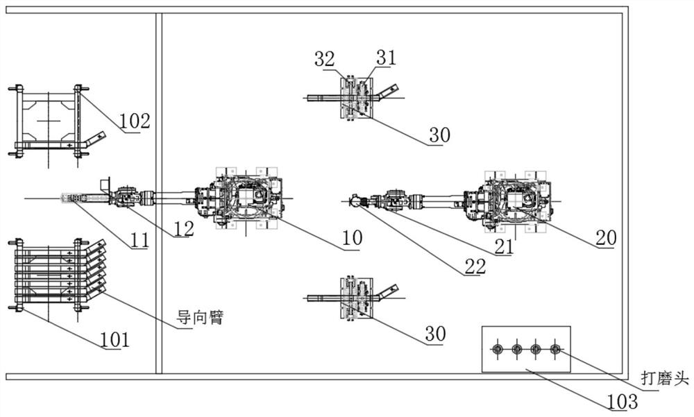
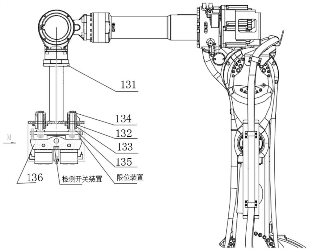
[0080] S1: The first robot moves to the top of the feeding rack, and the visual inspection device scans the guide arm once, determines the position of the guide arm, and guides the mechanical gripper on the first robot to grab the guide arm to the grinding table;

[0081] S2: The guide arm is on the grinding table, one end is supported on the support block, and the other end is supported on the fixture seat of the second clamping device. After the mechanical gripper releases the guiding arm, the first clamping device and the second clamping device Clamp the guide arm from the width direction and the thickness direction respectively;

[0082] S3: The first robot moves above the clamped guide arm, and the visual inspection device scans the guide arm twice to obtain the detailed geometric features of the grinding part, upload it to the host computer system, generate the grinding path and transmit it to the second ...

Embodiment 2

[0086] Example 2 (based on two grinding tables)

[0087] In order to further improve the grinding efficiency, this solution specially sets up two grinding tables, that is, the grinding table includes a first grinding table and a second grinding table, and the two grinding tables are symmetrically distributed between the first robot and the second robot. Based on two grinding tables, the specific grinding includes the following steps:

[0088] S1: The first robot moves to the top of the feeding rack, and the visual inspection device scans the guide arm once, determines the position of the guide arm, and guides the mechanical gripper on the first robot to grab the guide arm to the first grinding table;

[0089] S2: The guide arm is on the first grinding table, one end is supported on the support block, and the other end is supported on the clamp seat of the second clamping device. After the mechanical gripper releases the guiding arm, the first clamping device and the second cla...


PUM


Abstract

The invention discloses an automatic grinding system and a grinding method for a guide arm, and relates to the field of air suspension guide arm manufacturing, and specifically includes a first robot, the end of which is installed with a mechanical gripper; the first robot is used to realize the feeding of the guide arm and blanking; grinding table, used for the placement of the guide arm; the grinding table is provided with a first clamping device for clamping the width direction of the guiding arm and a second clamping device for clamping the thickness direction of the guiding arm ; the first robot places the guide arm on the grinding table and is clamped by the first clamping device and the second clamping device; and the second robot, the end of which is equipped with a constant force control device and a grinding device The second robot is used to realize the grinding of the guide arm; by setting the clamping device on the grinding table to realize the synchronous clamping of the guide arm up, down, left and right, which greatly promotes the improvement of the grinding quality; Improved grinding quality.

Description

technical field [0001] The invention relates to the field of air suspension guide arm manufacturing, in particular to an automatic guide arm grinding system and an automatic grinding method. Background technique [0002] The air suspension guide arm is an important part of commercial vehicles. It plays a bearing and guiding role in the air suspension. The force is complex, and its surface quality has a great influence on the fatigue life. The manufacturing of the guide arm needs to go through multiple thermal processing processes such as rolling, bending, torsion forming and heat treatment. Therefore, the three-dimensional size of the workpiece fluctuates greatly, and there are a few defects such as indentation and micro-cracks on the surface. [0003] In order to eliminate surface defects, the current method is to manually hoist the workpiece to the worktable with a spreader, and manually grind it with a hand-held angle grinder. The grinding quality depends on the operator'...

Claims


Application Information

Patent Timeline
Patent Type & Authority Patents(China)
IPC IPC(8): B24B27/00B24B41/06B24B41/00B24B51/00B24B1/00B25J11/00
CPCB24B27/0076B24B27/0092B24B41/06B24B41/005B24B41/00B24B51/00B24B1/00B25J11/0065
Inventor 王爱民石朝阳朱云龙申回春
Owner 东风汽车底盘系统有限公司
Learn More