Copper foil production equipment
A production equipment and technology of copper foil, which is applied in the field of copper foil slitting and winding, can solve problems such as bending, inability to guarantee the quality of copper foil, and vibration of copper foil up and down, and achieve the effects of reducing up and down vibration, improving practicability, and improving efficiency
- Summary
- Abstract
- Description
- Claims
- Application Information
AI Technical Summary
Problems solved by technology
Method used
Image
Examples
Embodiment 1
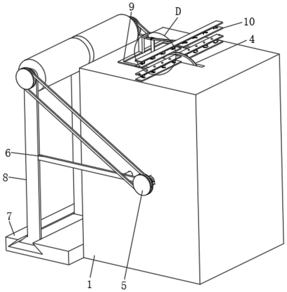
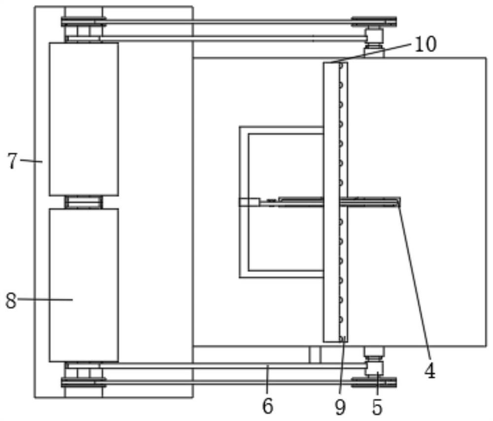
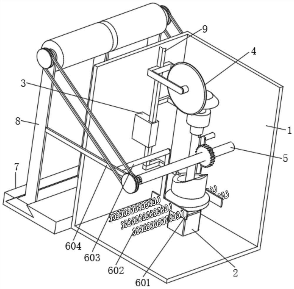
[0043] see Figure 1 to Figure 3 and Figure 8 , the embodiment of the present invention provides copper foil production equipment: a drive assembly 2 is fixedly installed inside the housing 1, and the drive assembly 2 includes a cylindrical cam 204, a first spline shaft 205, and a first The spline sleeve 206, the first helical gear 207 fixedly installed on the top of the first spline sleeve 206 and the first ferrule 208 rotatably installed on the outer surface of the first spline sleeve 206, the inside of the housing 1 is fixedly installed with a cylinder Cam 204 movably cooperates with the adjustment assembly 3 fixedly connected with the first ferrule 208, the top of the adjustment assembly 3 is fixedly installed with the cutting assembly 4 meshing with the first helical gear 207, and the top of the cutting assembly 4 is fixedly installed with an extension shell The lower limit assembly 9 of the body 1, the top of the housing 1 is fixedly installed with the upper limit asse...
Embodiment 2
[0048] see image 3 , Figure 7 and Figure 8 , on the basis of Embodiment 1, the drive assembly 2 further includes a motor 201, the motor 201 is fixedly connected to the inner wall of the housing 1, the output shaft of the motor 201 is fixedly installed with a worm 202, and the outer surface of the worm 202 is fixedly sleeved with a plane cam 203 , the cylindrical cam 204 is fixedly installed on the outer surface of the worm 202 , and the end of the worm 202 away from the motor 201 is fixedly connected with the first spline shaft 205 .
[0049] In this embodiment, preferably: when in use, the driving motor 201 drives the worm 202 to rotate, and the worm 202 drives the plane cam 203, the cylindrical cam 204 and the first spline shaft 205 to move synchronously, and the first spline shaft 205 passes through the first spline The sleeve 206 and the first helical gear 207 drive the cutting assembly 4 to rotate, and through the cooperation of the cylindrical cam 204, the first fer...
Embodiment 3
[0051] see image 3 , Figure 4 , Figure 7 and Figure 8 , on the basis of the second embodiment, the adjustment assembly 3 includes a block 301, which is fixedly connected to the inner wall of the housing 1, the surface of the block 301 penetrates and is slidably installed with a slide bar 302, and the side wall of the slide bar 302 is fixedly installed with a second A connecting rod 303 and a second connecting rod 304 , the first connecting rod 303 is fixedly connected with the first ferrule 208 , and the second connecting rod 304 is movably matched with the cylindrical cam 204 .
[0052] In this embodiment, preferably: the rotation of the cylindrical cam 204 during use, in conjunction with the action of gravity, can drive the second connecting rod 304 to reciprocate up and down, and the second connecting rod 304 drives the sliding rod 302 and the first connecting rod 303 to move up and down synchronously , the sliding rod 302 drives the cutting assembly 4 to move synchr...
PUM
 Abstract
Description
Claims
Application Information
 - R&D
- Intellectual Property
- Life Sciences
- Materials
- Tech Scout
- Unparalleled Data Quality
- Higher Quality Content
- 60% Fewer Hallucinations
Browse by: Latest US Patents, China's latest patents, Technical Efficacy Thesaurus, Application Domain, Technology Topic, Popular Technical Reports.
© 2025 PatSnap. All rights reserved.Legal|Privacy policy|Modern Slavery Act Transparency Statement|Sitemap|About US| Contact US: help@patsnap.com


