Gear heat treatment device for industrial production

A technology for heat treatment devices and gears, which is applied in heat treatment furnaces, heat treatment equipment, quenching devices, etc., can solve problems such as residual impurities, damaged workpieces, and gears that are not heated to the expected effect, and achieve the effect of increased hardness and toughness, and improved work

Pending Publication Date: 2021-11-09
刘熔
View PDF13 Cites 0 Cited by
  • Summary
  • Abstract
  • Description
  • Claims
  • Application Information

AI Technical Summary

Problems solved by technology

[0005] In order to overcome the fact that most of the existing heat treatment devices on the market have the advantages of convenient operation, some impurities will inevitably remain on the gear during the heat treatment of the gear, so that the gear cannot be heated in all directions, so that the gear cannot be heated to achieve the desired effect or The shortcoming of damaging the workpiece, the technical problem to be solved is: to provide an industrial gear heat treatment device for automatic heating, automatic transportation and automatic quenching

Method used


Image

  • Gear heat treatment device for industrial production
  • Gear heat treatment device for industrial production
  • Gear heat treatment device for industrial production

Examples


Embodiment 1

[0076] A gear heat treatment device for industrial production, such as Figure 1-5 As shown, it includes a support block 1, an electromagnetic heating ring 2, a push mechanism 3, a press mechanism 4 and a rotation mechanism 5. The support block 1 is provided with a push mechanism 3, and the push mechanism 3 is provided with a press mechanism 4, which is pressed down. The mechanism 4 cooperates with the pushing mechanism 3, and the upper middle part of the support block 1 is provided with a rotating mechanism 5, and the electromagnetic heating coil 2 is installed on the rotating mechanism 5.

[0077] When the gears need heat treatment, this device can be used. The worker first superimposes multiple gears on the upper front side of the support block 1, starts the operation of the pushing mechanism 3, and the pushing mechanism 3 drives the operation of the pressing mechanism 4, and the pressing mechanism 4 operates to the gear. When the push mechanism 3 drives the push-down mecha...

Embodiment 2

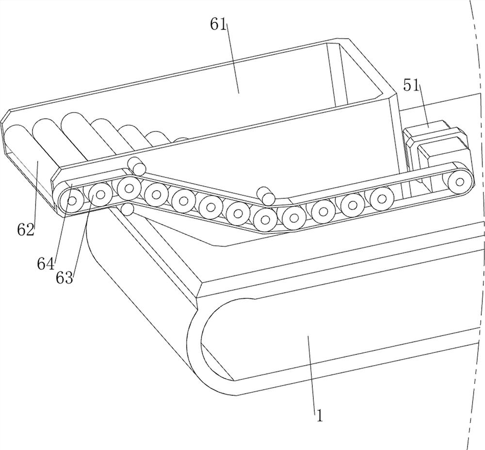
[0085] On the basis of Example 1, such as Figure 6-10 As shown, also includes transmission mechanism 6, and transmission mechanism 6 includes water tank 61, transmission roller 62, synchronous wheel 63 and synchronous belt 64, and support block 1 upper rear side is provided with water tank 61, and the rotation type on water tank 61 is provided with 12 The transmission rollers 62, the left side of the 12 transmission rollers 62 and the output shaft of the servo motor 51 are all provided with a synchronous wheel 63, and a synchronous belt 64 is connected between the 13 synchronous wheels 63.

[0086] The worker first pours an appropriate amount of water into the water tank 61. After the gear is heated, the program will control the electromagnet 45 to energize. The electromagnet 45 will pick up the gear and move backward. When the gear moves backward to the top of the water tank 61, The program will control the electromagnet 45 to be powered off, the electromagnet 45 will not ho...


PUM


Abstract

The invention relates to a treatment device, in particular to a gear heat treatment device for industrial production. The gear heat treatment device for industrial production can achieve automatic heating, automatic conveying and automatic quenching. The gear heat treatment device for industrial production comprises a supporting block, a pushing mechanism, a downward pressing mechanism, a rotating mechanism and an electromagnetic heating ring; the pushing mechanism is arranged on the supporting block; the pushing mechanism is provided with the downward pressing mechanism, and the downward pressing mechanism is matched with the pushing mechanism; the rotating mechanism is arranged in the middle of the upper side of the supporting block; and the electromagnetic heating ring is mounted on the rotating mechanism. According to the gear heat treatment device for industrial production, through the arrangement of the pushing mechanism, the pushing mechanism and the downward pressing mechanism can achieve conveying and downward pressing work of gears; through cooperation of the rotating mechanism and the conveying mechanism, the gears can be heated, and meanwhile the hardness and toughness of the gears are improved; and through cooperation of the rotating mechanism and a cleaning mechanism, the gears can be cleaned, and meanwhile the rotating mechanism can be cleaned.

Description

technical field [0001] The invention relates to a treatment device, in particular to a gear heat treatment device for industrial production. Background technique [0002] A gear is a mechanical element with teeth on the rim that can continuously mesh to transmit motion and power. It is a toothed mechanical part that can mesh with each other. The diameter of the large gear is twice the diameter of the small gear. With the development of production, gear heat treatment The device has received more and more attention, but most of the existing heat treatment devices on the market have the advantage of easy operation. During the heat treatment of the gear, it is inevitable that some impurities will remain on the gear, so that the gear cannot be heated in all directions, thus Heating the gear will not achieve the desired effect or damage the workpiece. [0003] Patent application number: CN210886151U, discloses a gear heat treatment equipment that is easy to operate, including an...

Claims


Application Information

Patent Timeline
IPC IPC(8): C21D9/32C21D1/63C21D1/10B08B1/00
CPCC21D9/32C21D9/0062C21D1/10C21D1/63B08B1/12Y02P10/25
Inventor 刘熔
Owner 刘熔
Why Eureka
Try Eureka