Cast-in-place frame column reinforcement cage prefabricated assembly type construction reinforcing device

A technology for strengthening devices and frame columns, which is applied to building reinforcements, processing of building materials, construction, etc., can solve problems such as affecting verticality, unfavorable construction use, reducing strength, etc. Conducive to the effect of construction reinforcement

Pending Publication Date: 2021-11-09
刘宗远
View PDF6 Cites 0 Cited by
  • Summary
  • Abstract
  • Description
  • Claims
  • Application Information

AI Technical Summary

Problems solved by technology

[0003] However, most of the existing steel cage prefabricated construction devices are simple supporting plate structures. When in use, multiple longitudinal steel bars cannot be stably positioned to maintain the cage shape, and the length of the steel bars is too long to cause one end to sag when two ends cannot be supported. However, it affects the verticality, resulting in poor binding quality, and cannot be stably tightened for binding and shaping, which is not conducive to the stable connection of horizontal steel bars, affects the compactness of the overall structure, causes the cage structure to loosen and reduces the strength, which is not conducive to construction and use, and needs to be carried out. Improve

Method used


Image

  • Cast-in-place frame column reinforcement cage prefabricated assembly type construction reinforcing device
  • Cast-in-place frame column reinforcement cage prefabricated assembly type construction reinforcing device
  • Cast-in-place frame column reinforcement cage prefabricated assembly type construction reinforcing device

Examples


Embodiment Construction

[0032] The following will clearly and completely describe the technical solutions in the embodiments of the present invention in conjunction with the accompanying drawings in the embodiments of the present invention; obviously, the described embodiments are only part of the embodiments of the present invention, not all embodiments, based on The embodiments of the present invention and all other embodiments obtained by persons of ordinary skill in the art without making creative efforts belong to the protection scope of the present invention.

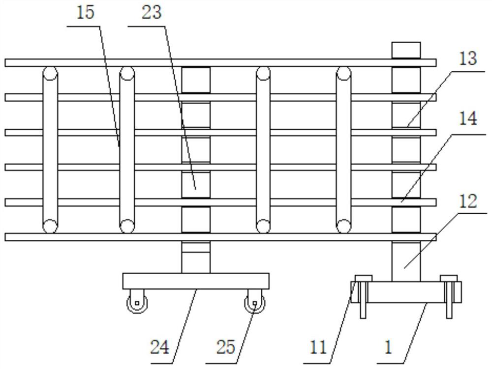
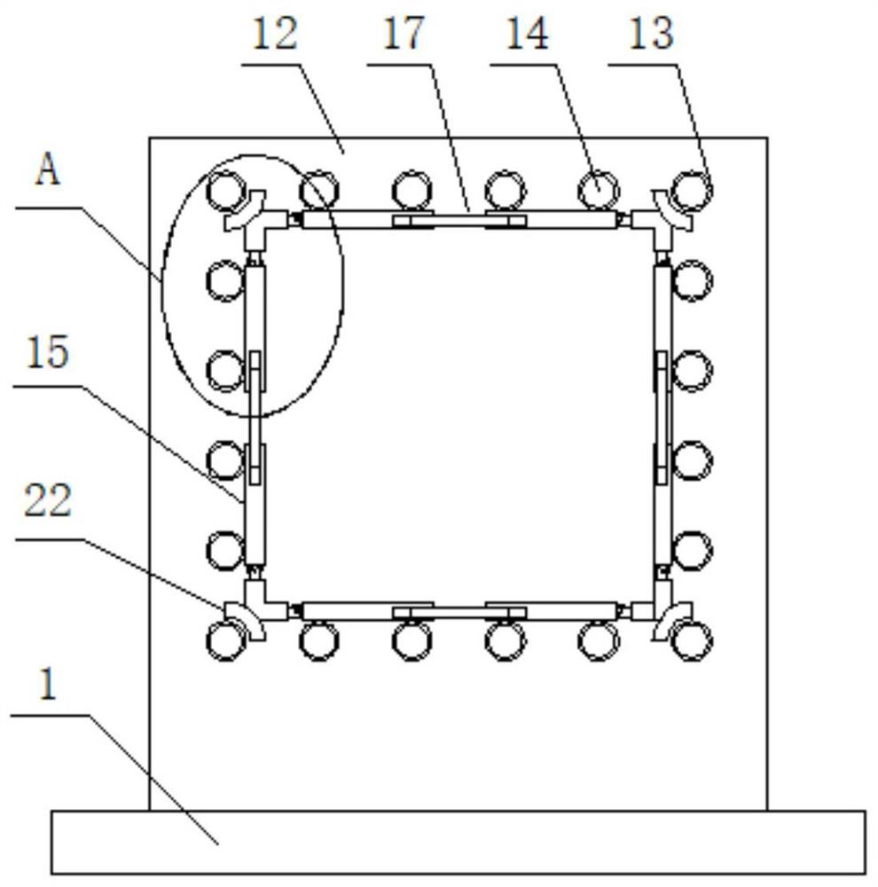
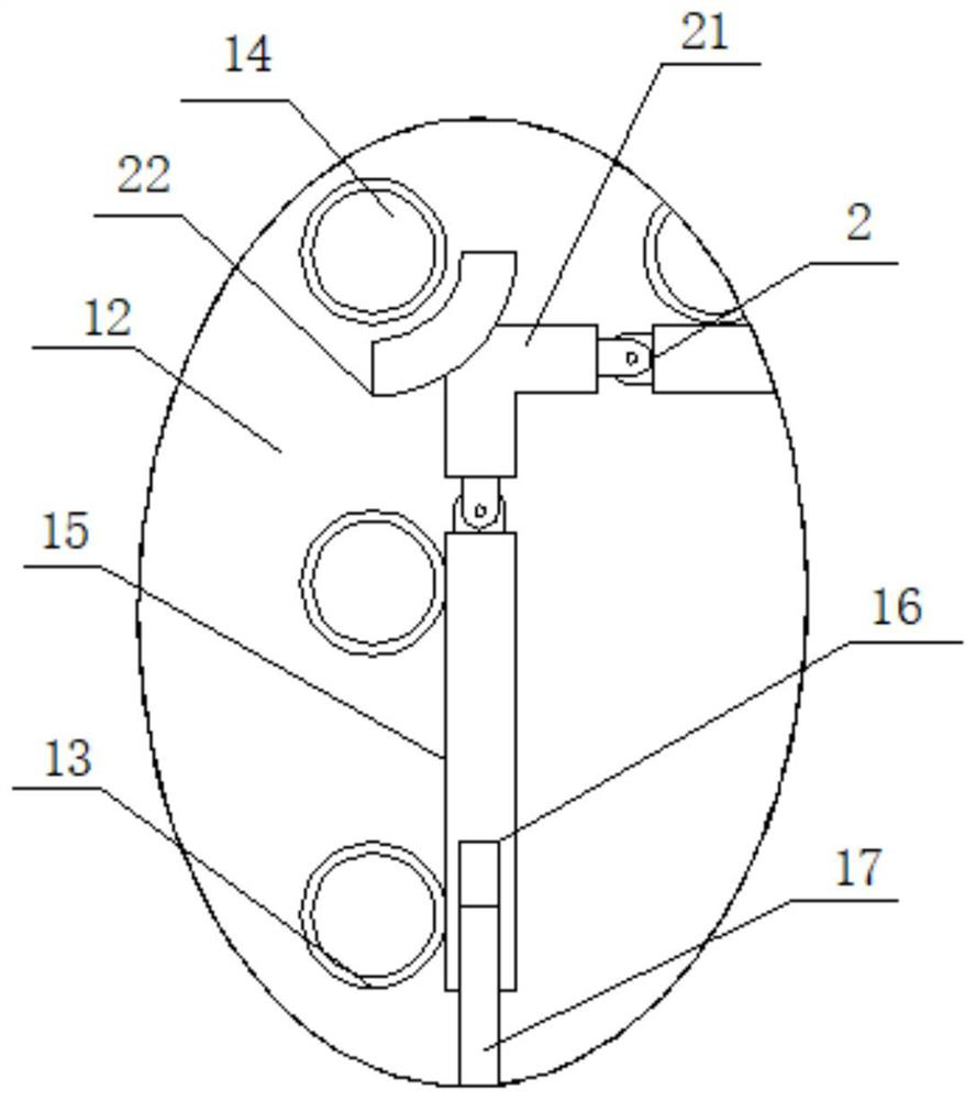
[0033] see Figure 1-5 , a prefabricated construction strengthening device for cast-in-place frame column reinforcement cage, including fixing plate 1, see figure 1 , figure 2 with image 3 , both ends of one side surface of the fixed plate 1 are fixedly connected with fixing screws 11, one side surface of the fixed plate 1 is fixedly connected with a support plate 12, the surface of the support plate 12 is provided with a through hol...


PUM


Abstract

The invention discloses a cast-in-place frame column reinforcement cage prefabricated assembly type construction reinforcing device. The device comprises a fixing plate, wherein fixing screws are fixedly connected to the two ends of the surface of one side of the fixing plate, a supporting plate is fixedly connected to the surface of one side of the fixing plate, through holes are formed in the surface of the supporting plate, longitudinal steel bars are inserted into the side faces of the through holes, the longitudinal steel bars are combined to form a steel bar cage frame, supporting rods are connected to the surfaces of one sides of the longitudinal steel bars in an abutting mode, threaded holes are formed in the surfaces of one ends of the supporting rods, lengthened threaded rods are connected to the side faces of the threaded holes in a threaded mode, the lengthened threaded rods are located on one sides of the longitudinal steel bars, hinge shafts are arranged on the surfaces of the other ends of the supporting rods, right-angle rods are hinged to the surfaces of the hinge shafts, and arc-shaped blocks are fixedly welded to the corner positions of the surfaces of one sides of the right-angle rods, so that use convenience and stability can be greatly improved, and safety and high efficiency of prefabrication construction are guaranteed.

Description

technical field [0001] The invention relates to the field of reinforcement cages, and more specifically relates to a prefabricated construction reinforcement device for reinforcement cages of cast-in-place frame columns. Background technique [0002] In the process of pouring construction, steel cages are needed as reinforcement structures, and in order to facilitate efficient construction, it is necessary to prefabricate steel cages off-site, and in order to ensure the structural stability of steel cages, it is necessary to use reinforcement structures to assist fabrication. [0003] However, most of the existing steel cage prefabricated construction devices are simple supporting plate structures. When in use, multiple longitudinal steel bars cannot be stably positioned to maintain the cage shape, and the length of the steel bars is too long to cause one end to sag when two ends cannot be supported. However, it affects the verticality, resulting in poor binding quality, and...

Claims


Application Information

Patent Timeline
Patent Type & Authority Applications(China)
IPC IPC(8): E04G21/12E04C5/06
CPCE04G21/12E04C5/06
Inventor 不公告发明人
Owner 刘宗远
Why Eureka
Try Eureka