Quick-heating central air conditioner water circulation control system and method

A central air-conditioning and control system technology, applied in heating and ventilation control systems, control input related to air characteristics, space heating and ventilation control input, etc., can solve the problems of increased energy consumption, long time, etc., to improve indoor temperature , Improve the overall energy efficiency

Active Publication Date: 2021-11-09
STATE GRID JIANGSU ELECTRIC POWER CO ELECTRIC POWER RES INST +1
View PDF6 Cites 0 Cited by
  • Summary
  • Abstract
  • Description
  • Claims
  • Application Information

AI Technical Summary

Problems solved by technology

[0003]During the regulation process, since the temperature difference between the hot water provided and the user side is not high, the maximum water volume is limited by the pressure between the dry water supply pipe and the dry return pipe, and the user side It takes a long time for the indoor fan coil unit to start from the shutdown state until the room temperature reaches the set value. Long-term operation or early operation, which greatly increases energy consumption

Method used


Image

  • Quick-heating central air conditioner water circulation control system and method
  • Quick-heating central air conditioner water circulation control system and method
  • Quick-heating central air conditioner water circulation control system and method

Examples


Embodiment 1

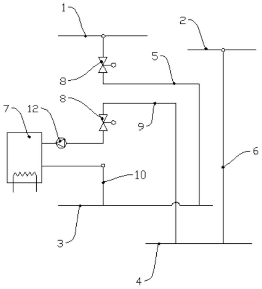
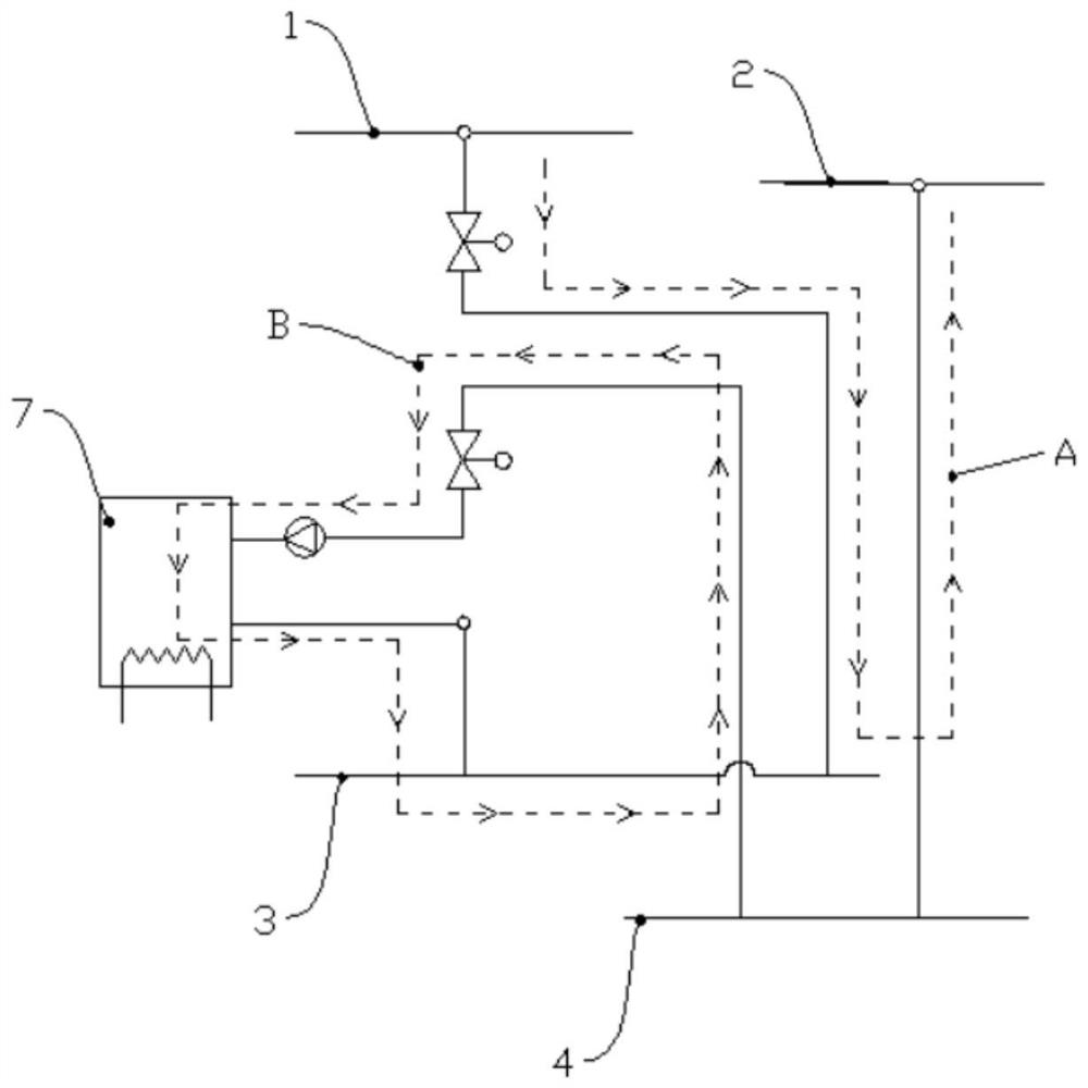
[0059] A water cycle control system for central air-conditioning with rapid temperature rise, which is connected to the dry water supply pipe 1 and the dry return pipe 2 of the central air-conditioning control system, and the indoor water supply pipe 3 and the indoor return water pipe 4 on the user side, wherein the indoor water supply pipe 3 and the indoor water return pipe 4 The indoor return water pipes 4 are respectively connected to the indoor fan coils; including: the first water circulation system, realizing the water circulation between the dry water supply pipe 1, the indoor water supply pipe 3, the indoor fan coil, the indoor return water pipe 4 and the dry return water pipe 2; The second water circulation system is provided with an electric hot water tank 7, and realizes water circulation between the indoor water supply pipe 3, the indoor fan coil unit, the indoor water return pipe 4 and the electric hot water tank 7.

[0060] As far as the installation method is con...

Embodiment 2

[0063] In this example, if Figure 1~3 As shown, on the basis of Embodiment 1, a specific pipeline connection method of a central air-conditioning water circulation control system with rapid temperature rise is provided:

[0064] The first water circulation system includes: a first pipeline 5, connecting the dry water supply pipe 1 and the indoor water supply pipe 3; a second pipeline 6, connecting the dry return pipe 2 and the indoor return water pipe 4; the first pipeline 5 is provided with an electric control The two-way valve 8, the water supply flows from the dry water supply pipe 1 to the indoor water supply pipe 3.

[0065] The first water circulation system in this embodiment can use the pipeline form of the existing system. At present, the above-mentioned pipeline form is used to supply hot water to the indoor fan coil unit, so no additional construction is required. The indoor water supply pipe 3 and the indoor water return pipe 4 are branch structures corresponding...

Embodiment 3

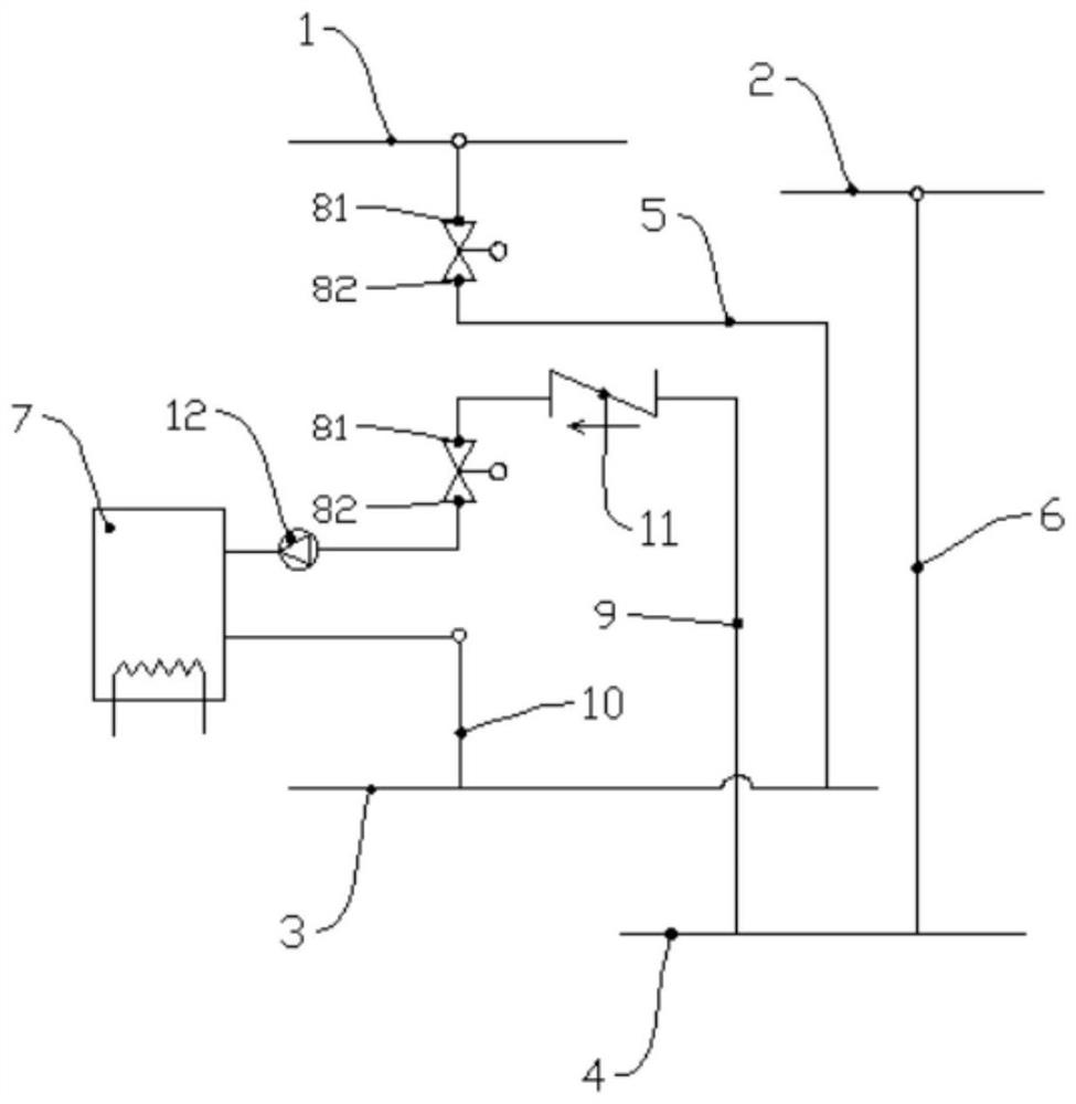
[0073] In this embodiment, on the basis of Embodiment 1, as Figure 4~6 As shown, with respect to embodiment two, another specific pipeline connection method of the central air-conditioning water circulation control system with rapid temperature rise is provided:

[0074] The first water circulation system includes: a first pipeline 5, connecting the dry water supply pipe 1 and the indoor water supply pipe 3; a second pipeline 6, connecting the dry return water pipe 2 and the indoor return water pipe 4; see Figure 5 , the second water circulation system includes: connecting pipeline 13, connecting the first pipeline 5 and the second pipeline 6, the first connecting point 51 of the connecting pipeline 13 and the first pipeline 5 divides the first pipeline 5 into and The first section 52 connected to the dry water supply pipe 1, and the second section 53 connected to the indoor water supply pipe 3, the first section 52 is provided with an electronically controlled two-way valve...


PUM


Abstract

The invention belongs to the technical field of comprehensive energy, and particularly relates to a quick-heating central air conditioner water circulation control system. The system comprises a first water circulation system and a second water circulation system. The first water circulation system achieves water circulation among a dry water supply pipe, an indoor water supply pipe, an indoor fan coil, an indoor water return pipe and a dry water return pipe; and the second water circulation system is provided with an electric heating water tank, and achieves water circulation among the indoor water supply pipe, the indoor fan coil, the indoor water return pipe and the electric heating water tank. The quick-heating central air conditioner water circulation control system can be directly connected between an existing central air conditioner control system and the indoor fan coil in series, and the influence on normal operation of an existing central air conditioner is avoided; and in the working process, the indoor temperature can be rapidly increased through the second water circulation system, long-term operation of the system is not needed while good experience of a user is maintained, and the comprehensive energy utilization efficiency of the system is improved. The invention further discloses a quick-heating central air conditioner water circulation control method which has the same advantages.

Description

technical field [0001] The invention belongs to the technical field of comprehensive energy, and in particular relates to a central air-conditioning water cycle control system and control method for rapid temperature rise. Background technique [0002] At present, the central air conditioner under the heating condition provides hot water with a medium temperature of about 50 degrees Celsius to the indoor fan coil unit on the user side through the water supply pipeline and the return water pipeline. The water supply and return water volume of the fan coil unit can effectively control the temperature of the user side. [0003] During the control process, since the temperature difference between the hot water provided and the user side temperature is not high, the maximum water volume is limited by the pressure between the dry water supply pipe and the dry return water pipe. In this case, in order to ensure that the user side can quickly obtain a suitable temperature when need...

Claims


Application Information

Patent Timeline
Patent Type & Authority Applications(China)
IPC IPC(8): F24F11/30F24F11/64F24F11/84F24F11/85F24F11/873F24F11/88F24F110/10
CPCF24F11/30F24F11/64F24F11/84F24F11/85F24F11/873F24F11/88F24F2110/10
Inventor 孙天奎袁宇波史明明方鑫庄舒仪苏伟袁晓冬孙健张宸宇肖小龙杨景刚高磊李鹏陈静陈舒刘建李群
Owner STATE GRID JIANGSU ELECTRIC POWER CO ELECTRIC POWER RES INST
Why Eureka
Try Eureka