Broadband coupling patch antenna with consistent radiation pattern and improved gain

A radiation direction, coupling patch technology, applied in the antenna grounding device, the radiating element structure, the antenna grounding switch structure connection and other directions, can solve the problem of the radiation pattern shape cannot be consistent, the gain is low, the bandwidth is narrow, etc. The effect of consistent internal radiation pattern, low cross-polarization, and wide working bandwidth

Active Publication Date: 2021-11-09
深圳电目科技有限公司
View PDF5 Cites 7 Cited by
  • Summary
  • Abstract
  • Description
  • Claims
  • Application Information

AI Technical Summary

Problems solved by technology

However, the traditional microstrip patch antenna has two major disadvantages: narrow bandwidth and low gain, which makes it difficult to apply to broadband communication and medium and long-distance communication
However, when multiple radiation patterns are brought together to form a broadband, the radiation pattern shape within the band cannot be kept consistent

Method used


Image

  • Broadband coupling patch antenna with consistent radiation pattern and improved gain
  • Broadband coupling patch antenna with consistent radiation pattern and improved gain
  • Broadband coupling patch antenna with consistent radiation pattern and improved gain

Examples


Embodiment 1

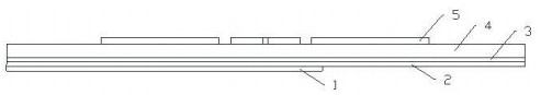
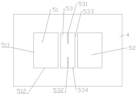
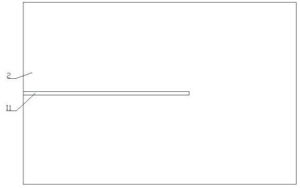
[0039] see Figure 1 to Figure 4 , a broadband coupling patch antenna with a consistent radiation pattern and increased gain, comprising a sequentially stacked feed network layer 1, a first dielectric layer 2, a metal floor 3, a second dielectric layer 4 and a radiation layer 5; The radiation layer 5 is provided with a main patch 53, a first parasitic patch 51 and a second parasitic patch 52, the metal floor 3 is provided with a hollow groove 31, and the feed network layer 1 is provided with a microstrip feeder 11; The microstrip feeder 11 is coupled to the main patch 53 through the hollow groove 31, and the main patch 53 is respectively coupled to the first parasitic patch 51 and the second parasitic patch 52; The main patch 53 is provided with a slit group for keeping the radiation direction consistent; the slit group is composed of N slits located on the same straight line, and the straight line passes through the center of the main patch 53; the first parasitic sticker Th...

Embodiment 2

[0042] On the basis of the above structure, the first projection of the center of the main patch 53 coincides with the center of the hollow groove 31; the hollow groove 31 is a rectangular groove, and the straight line is parallel to the length direction of the rectangular groove, further Improved broadband radiation and stable radiation pattern characteristics.

Embodiment 3

[0044] On the basis of the above structure, the slit group is composed of a first slit 531 and a second slit 532; one end of the first slit 531 extends to one edge of the main patch 53, and one end of the second slit 532 Extending to the other edge of the main patch 53 ; the first slit 531 and the second slit 532 are symmetrical about the center of the main patch 53 , further improving broadband radiation and stable radiation pattern characteristics.


PUM


Abstract

The invention provides a broadband coupling patch antenna with a consistent radiation pattern and improved gain. The broadband coupling patch antenna comprises a feed network layer, a first dielectric layer, a metal floor, a second dielectric layer and a radiation layer which are stacked in sequence. The radiation layer is provided with a main patch, a first parasitic patch and a second parasitic patch, the metal floor is provided with a hollow groove, and the feed network layer is provided with a microstrip feeder line. The microstrip feeder line is coupled with the main patch through the hollow groove, and the main patch is coupled with the first parasitic patch and the second parasitic patch separately. The main patch is provided with a gap group for keeping consistent radiation patterns. The gap group is composed of N gaps located on the same straight line, and the straight line passes through the center of the main patch. The first parasitic patch and the second parasitic patch are in mirror symmetry about a straight line. N is a natural number greater than or equal to 1. Under the synergistic effect of the microstrip feeder line, the hollow groove, the main patch, the gap group and the two parasitic patches, the antenna has the characteristics of low cross polarization, wide working bandwidth, improved gain and consistent in-band radiation pattern.

Description

technical field [0001] The invention relates to the technical field of microwave communication, in particular to a broadband coupling patch antenna with a consistent radiation pattern and improved gain. Background technique [0002] In recent years, with the rapid development of wireless communication and increasingly complex application scenarios, the bandwidth and other performance requirements of antennas in wireless communication systems are getting higher and higher. Microstrip patch antennas are widely used in various wireless communications due to their advantages of low profile, light weight, easy processing and low cost. However, the traditional microstrip patch antenna has two major disadvantages: narrow bandwidth and low gain, which makes it difficult to apply to broadband communication and medium and long-distance communication. [0003] In recent decades, many scholars at home and abroad have done a lot of research on patch antennas to improve the bandwidth of ...

Claims


Application Information

Patent Timeline
Patent Type & Authority Applications(China)
IPC IPC(8): H01Q1/50H01Q1/38H01Q1/48
CPCH01Q1/50H01Q1/38H01Q1/48
Inventor 张晓李国雄袁涛
Owner 深圳电目科技有限公司
Why Eureka
Try Eureka