Electric control cabinet with automatic early warning function
An automatic early warning and electric control cabinet technology, applied in the field of electric control cabinets, can solve problems such as damage, economic loss, and failure to detect in time, and achieve a wide range of applications
- Summary
- Abstract
- Description
- Claims
- Application Information
AI Technical Summary
Problems solved by technology
Method used
Image
Examples
Embodiment 1
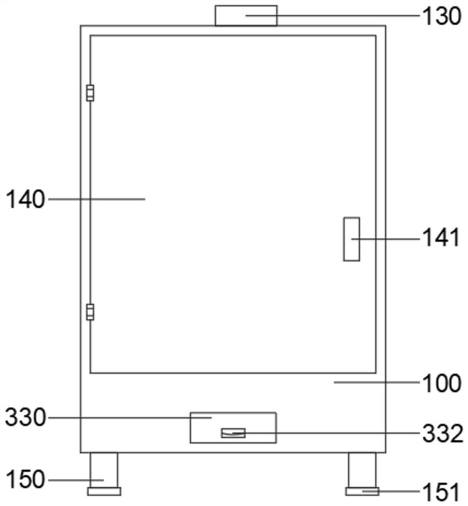
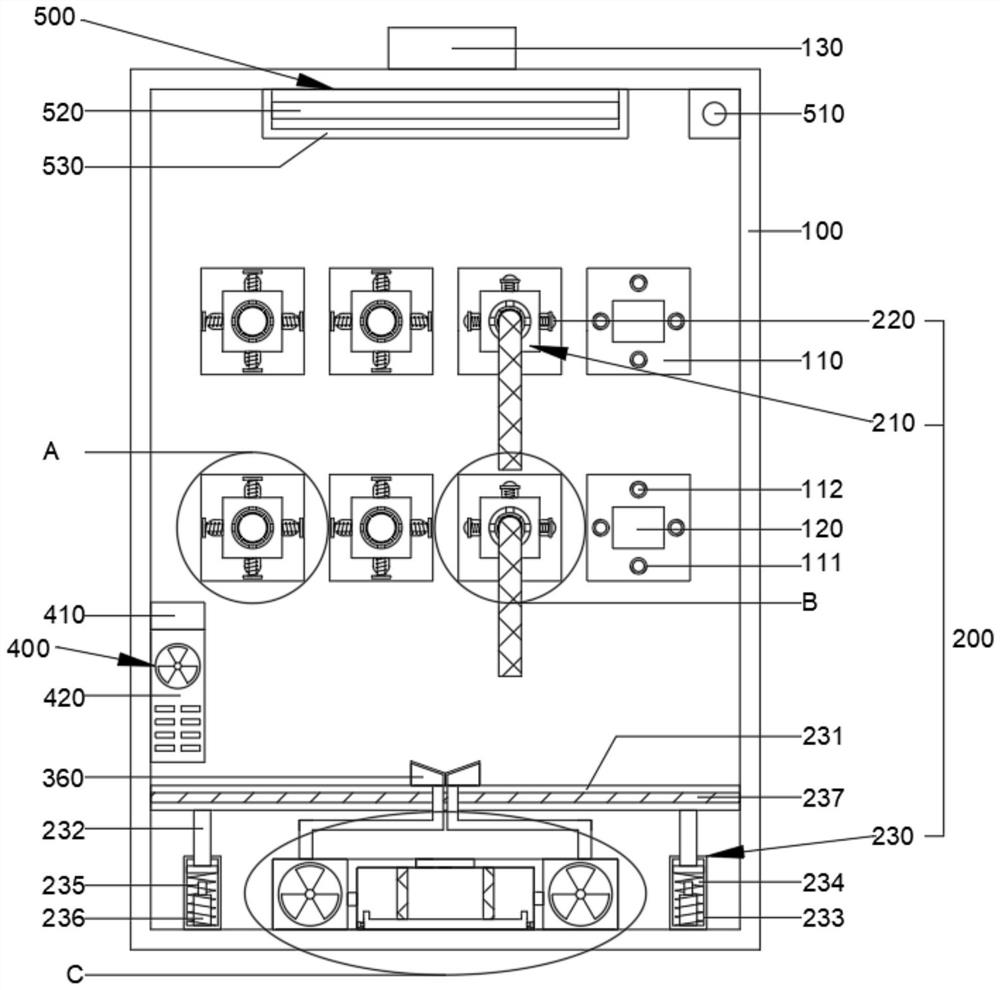
[0040] see again Figure 1-Figure 6 , the cabinet body 100, the rear wall of the interior is equidistant and rectangular and has eight installation seats 110 connected by bolts, and the front wall of the installation seat 110 is equidistant and circular with four jacks 111, and the inside of the jacks 111 The end is embedded with a piezoelectric sensor 112, the front wall of the mounting base 110 is embedded with an electrical slot 120, and the outer top of the cabinet 100 is connected with an alarm 130 by bolts;
[0041] The cable drop detection assembly 200 includes a cable clamping assembly 210, an insertion rod 220 and a drop detection assembly 230, the lower parts of the four side walls of the cable clamping assembly 210 are connected to the insertion rod 220 by bolts, and the insertion rod 220 is compatible with the jack 111, and the insertion rod 220 is attached to the piezoelectric sensor 112 when inserted into the end of the jack 111;
[0042] The drop detection asse...
Embodiment 2
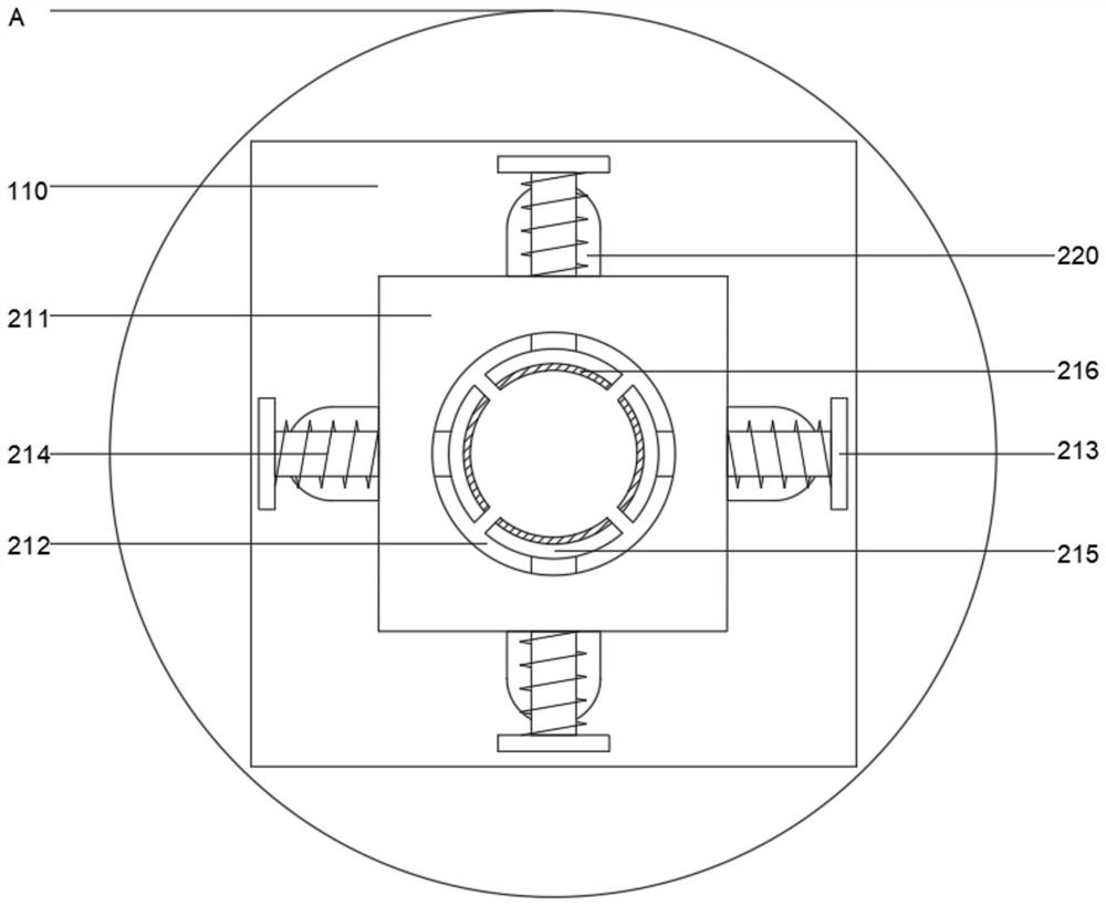
[0044] Example 2, see again Figure 1-Figure 6 , the difference from Embodiment 1 is that the cable clamping assembly 210 includes a fixing frame 211, a through hole 212, a clamping rod 213, a clamping spring 214 and a splint 215, and a through hole is opened in the middle of the fixing frame 211. The through hole 212 of the fixed frame 211 is slidingly connected to the middle of the four side walls of the fixed frame 211. The two ends of the clamped rod 213 are respectively located on the outside of the fixed frame 211 and in the through hole 212. One end of the rod 213 located in the through hole 212 is welded to the splint 215, one end of the clamping rod 213 located outside the fixed frame 211 is welded to one end of the clamping spring 214, and the other end of the clamped spring 214 is welded to the side wall of the fixed frame 211 ;
[0045] The fixing frame 211 is used to open a through hole 212 to fix other parts above. The through hole 212 is used to allow the cable...
Embodiment 3
[0046] Example 3, see again Figure 1-Figure 6 The difference from Example 1 is that a dust removal assembly 300 is installed at the bottom of the cabinet body 100, and the dust removal assembly 300 includes an exhaust fan 310, a dust removal chamber 320, a slide plate 330, a filter screen 340, and an air intake hose 350 and the air inlet 360, the two exhaust fans 310 and the dust removal chamber 320 are all connected to the bottom of the cabinet body 100 by bolts, and the dust removal chamber 320 is connected by a pipeline between the two exhaust fans 310, and the dust removal chamber 320 There is an air outlet 321 at the top of the top of the dust removal chamber 320, and a slide plate 330 is provided at the inner bottom of the dust removal chamber 320. Both sides of the slide plate 330 are slidably connected with slide rails 331, and the two slide rails 331 are connected to the dust removal chamber 320 by bolts. , the front wall of the slide plate 330 is provided with a buc...
PUM
 Abstract
Description
Claims
Application Information
 - R&D
- Intellectual Property
- Life Sciences
- Materials
- Tech Scout
- Unparalleled Data Quality
- Higher Quality Content
- 60% Fewer Hallucinations
Browse by: Latest US Patents, China's latest patents, Technical Efficacy Thesaurus, Application Domain, Technology Topic, Popular Technical Reports.
© 2025 PatSnap. All rights reserved.Legal|Privacy policy|Modern Slavery Act Transparency Statement|Sitemap|About US| Contact US: help@patsnap.com


