All-dimensional spraying device capable of avoiding coating condensation
A spraying device and an all-round technology, applied in the direction of spraying devices, liquid spraying devices, etc., can solve problems such as difficult uniform spraying, easy solidification of paint, equipment blockage, etc., and achieve the effects of improving processing efficiency, avoiding precipitation and condensation, and avoiding damage
- Summary
- Abstract
- Description
- Claims
- Application Information
AI Technical Summary
Problems solved by technology
Method used
Image
Examples
Embodiment 1
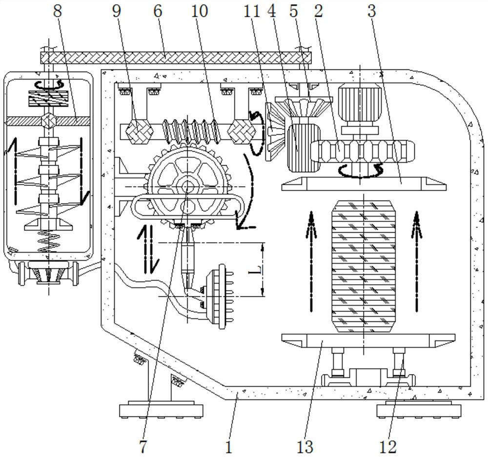
[0024] see figure 1 , figure 2 , the top inside the device box 1 is rotatably connected to the drive tooth 2, the bottom of the drive tooth 2 is welded with the pressure plate 3, the side of the drive tooth 2 is meshed with the driven wheel 4, the top of the driven wheel 4 is welded with the driven tooth 5, and the driven wheel 4 A belt 6 is sleeved on the periphery of the belt, the drive tooth 2 is horizontally connected to the middle position of the top inside the device box 1, and the pressure plate 3 is welded to the bottom of the drive tooth 2 in a horizontal state;
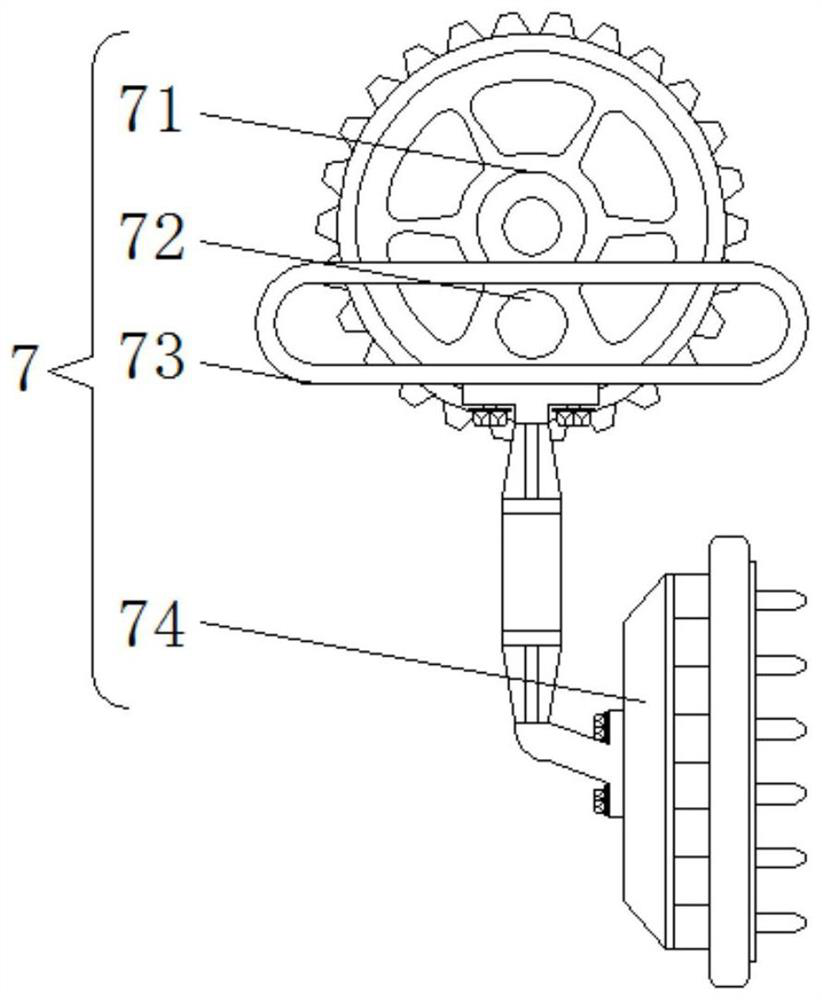
[0025] The belt 6 is sleeved on the top of the driven wheel 4, and placed outside the device case 1, the stirring shaft 83 and the driven wheel 4 are driven by the belt 6; the side of the device case 1 is provided with a spraying mechanism 7, and the spraying mechanism 7 includes The driven plate 71, the front of the driven plate 71 is welded with a limit block 72, the periphery of the limit block 72 is sl...
Embodiment 2
[0029] see figure 1 , image 3 , the top inside the device box 1 is rotatably connected to the drive tooth 2, the bottom of the drive tooth 2 is welded with the pressure plate 3, the side of the drive tooth 2 is meshed with the driven wheel 4, the top of the driven wheel 4 is welded with the driven tooth 5, and the driven wheel 4 A belt 6 is sleeved on the periphery of the belt, the drive tooth 2 is horizontally connected to the middle position of the top inside the device box 1, and the pressure plate 3 is welded to the bottom of the drive tooth 2 in a horizontal state;
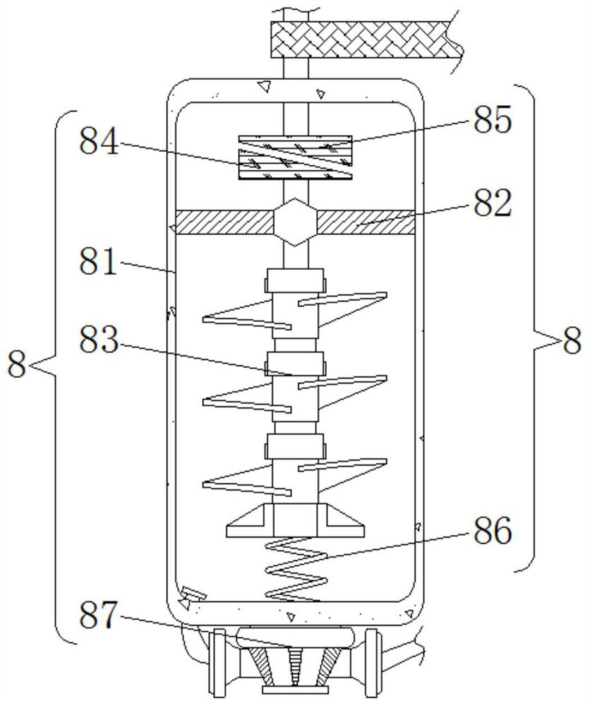
[0030] The belt 6 is sleeved on the top of the driven wheel 4, and placed outside the device case 1, the stirring shaft 83 and the driven wheel 4 are driven by the belt 6; Stirring mechanism 8 is arranged on the outside, and stirring mechanism 8 comprises sealed cabin 81, and the inside of sealed cabin 81 is welded with limiting plate 82, and the inner rotation of limiting plate 82 is connected with stirrin...
Embodiment 3
[0035] see Figure 1-3 , the top inside the device box 1 is rotatably connected to the drive tooth 2, the bottom of the drive tooth 2 is welded with the pressure plate 3, the side of the drive tooth 2 is meshed with the driven wheel 4, the top of the driven wheel 4 is welded with the driven tooth 5, and the driven wheel 4 A belt 6 is sleeved on the periphery of the belt, the drive tooth 2 is horizontally connected to the middle position of the top inside the device box 1, and the pressure plate 3 is welded to the bottom of the drive tooth 2 in a horizontal state;
[0036]The belt 6 is sleeved on the top of the driven wheel 4, and placed outside the device case 1, the stirring shaft 83 and the driven wheel 4 are driven by the belt 6; the side of the device case 1 is provided with a spraying mechanism 7, and the spraying mechanism 7 includes The driven plate 71, the front of the driven plate 71 is welded with a limit block 72, the periphery of the limit block 72 is sleeved with ...
PUM
 Abstract
Description
Claims
Application Information
 - R&D
- Intellectual Property
- Life Sciences
- Materials
- Tech Scout
- Unparalleled Data Quality
- Higher Quality Content
- 60% Fewer Hallucinations
Browse by: Latest US Patents, China's latest patents, Technical Efficacy Thesaurus, Application Domain, Technology Topic, Popular Technical Reports.
© 2025 PatSnap. All rights reserved.Legal|Privacy policy|Modern Slavery Act Transparency Statement|Sitemap|About US| Contact US: help@patsnap.com


