
Conductive auxiliary wheel device and line inspection robot using same

A technology of auxiliary wheel and conductive wheel, applied in overhead line/cable equipment, wheels, transportation and packaging, etc., can solve the problem of uninterrupted conduction, and achieve the effect of reducing pressure, preventing wear and prolonging service life

Pending Publication Date: 2021-11-12
GUANGDONG KEYSTAR INTELLIGENCE ROBOT CO LTD
View PDF8 Cites 0 Cited by
  • Summary
  • Abstract
  • Description
  • Claims
  • Application Information

AI Technical Summary

Problems solved by technology

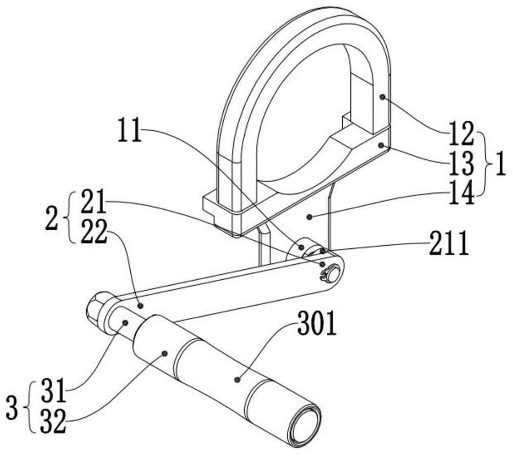
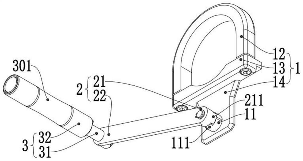
[0005] The purpose of the present invention is to propose a conductive auxiliary wheel device, which can effectively avoid damage to the transmission line under the premise of ensuring that the induced electric energy generated by the line inspection robot during inspection is guided away, and solves the problem of using metal road wheels in the existing Or the method of metal clamping wheel to guide the charge away, which may cause technical problems of wear and tear on the transmission line, the structure is simple and reasonable, and the performance is reliable
[0006] Another object of the present invention is to propose a line inspection robot using the above-mentioned conductive auxiliary wheel device, which solves the technical problem that it is difficult to achieve uninterrupted conduction in the existing method of using metal clamping wheels to guide the induced electricity away, which is beneficial to Adapt to the obstacle-crossing characteristics of the line inspection robot, easy and quick to install, to overcome the deficiencies in the existing technology

Method used


Image

  • Conductive auxiliary wheel device and line inspection robot using same
  • Conductive auxiliary wheel device and line inspection robot using same
  • Conductive auxiliary wheel device and line inspection robot using same

Examples


Embodiment Construction

[0031] Embodiments of the present invention are described in detail below, examples of which are shown in the drawings, wherein the same or similar reference numerals designate the same or similar elements or elements having the same or similar functions throughout. The embodiments described below by referring to the figures are exemplary only for explaining the present invention and should not be construed as limiting the present invention.

[0032] In describing the present invention, it should be understood that the terms "upper", "lower", "front", "rear", "left", "right", "top", "bottom", "inner", " The orientation or positional relationship indicated by "outside", etc. is based on the orientation or positional relationship shown in the drawings, and is only for the convenience of describing the present invention and simplifying the description, rather than indicating or implying that the referred device or element must have a specific orientation, so as to Specific orient...


PUM


Abstract

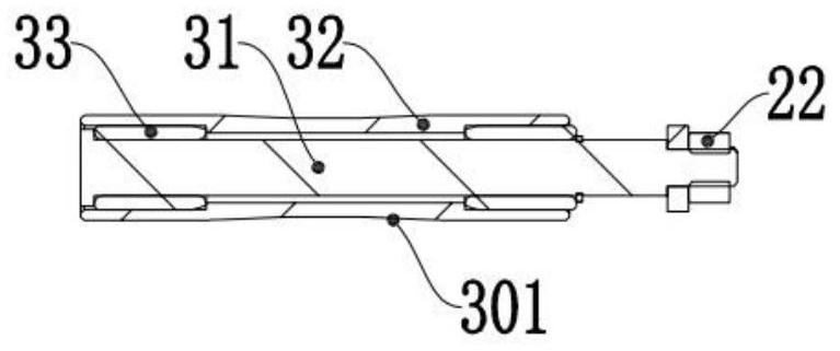
The invention discloses a conductive auxiliary wheel device and a line inspection robot using the conductive auxiliary wheel device, the conductive auxiliary wheel device comprises a conductive fixing assembly, a conductive connecting rod and a conductive assembly, the conductive connecting rod is installed between the conductive fixing assembly and the conductive assembly, and the conductive assembly is provided with a conductive surface; the conductive surface is used for guiding away induced electricity when abutting against the power transmission line; the conductive connecting rod is provided with a first connecting end and a second connecting end, the first connecting end is rotatably installed on the conductive fixing assembly, and the conductive assembly is rotatably connected to the second connecting end. According to the conductive auxiliary wheel device provided by the technical scheme, on the premise of ensuring that inductive electric energy generated by a line inspection robot during inspection is conducted away, damage to a power transmission line is effectively avoided. The line inspection robot solves the technical problem that an existing method for conducting away induced electricity through metal clamping wheels is difficult to achieve uninterrupted electricity conduction, and the line inspection robot is beneficial to adapting to the obstacle crossing characteristic of the line inspection robot.

Description

technical field [0001] The invention relates to the technical field of line inspection robots, in particular to a conductive auxiliary wheel device and a line inspection robot using the same. Background technique [0002] The transmission line is the artery of the power system, which is directly related to the development of the national economy and the normal life of the people, so its safe operation has been paid more and more attention by departments at all levels. Overhead transmission lines must not only bear the internal pressure of inherent mechanical loads and electrical loads, but also withstand various external aggressions from the natural environment, such as corrosion, pollution, lightning strikes, strong winds, floods, landslides, subsidence, earthquakes, and bird damage, as well as man-made destruction. Over time, various problems will inevitably occur on overhead transmission lines, such as broken wires, broken lightning conductors, tilted towers, flickering ...

Claims


Application Information

Patent Timeline
Patent Type & Authority Applications(China)
IPC IPC(8): B60B19/00H02G1/02
CPCB60B19/00H02G1/02
Inventor 邹霞李方付守海黎健源苏锦华樊广棉
Owner GUANGDONG KEYSTAR INTELLIGENCE ROBOT CO LTD
Learn More