Rail transit sanding system

A technology for rail transit and crushing sand, applied in the field of rail transit, can solve the problems of inability to sprinkle sand and crush, and achieve the effects of avoiding wet agglomeration, improving friction coefficient, and avoiding sand spreading and agglomeration

Active Publication Date: 2021-11-12
CCCC MECHANICAL & ELECTRICAL ENG
View PDF0 Cites 0 Cited by
  • Summary
  • Abstract
  • Description
  • Claims
  • Application Information

AI Technical Summary

Problems solved by technology

[0005] Aiming at the deficiencies of the prior art, the present invention provides a rail transit sanding system, which solves the problem that the existing sanding device cannot crush the agglomerated sand, improves the stability

Method used


Image

  • Rail transit sanding system
  • Rail transit sanding system
  • Rail transit sanding system

Examples


Embodiment 1

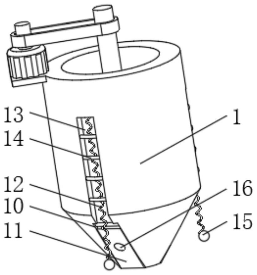
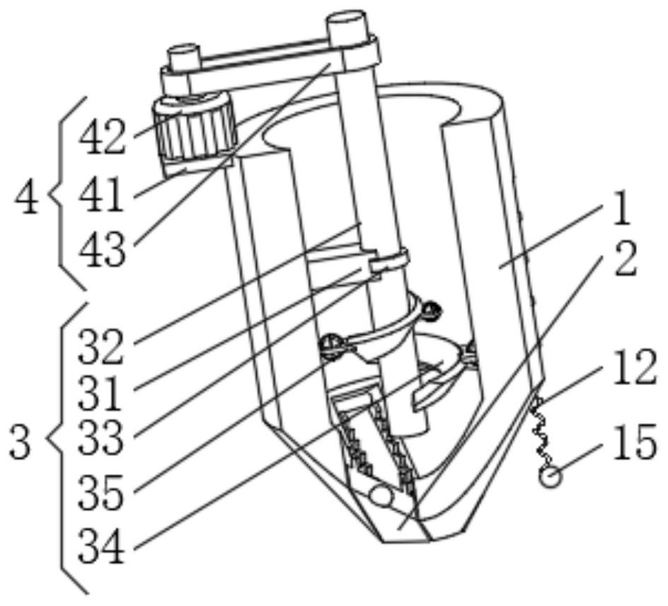
[0033] see Figure 1-5 , the present invention provides a technical solution: a rail transit sand spreading system, comprising a storage tank 1, the top of the storage tank 1 is designed as an opening, the bottom of the storage tank 1 is provided with a sand sprinkling port 2, and the storage tank 1 The internal settings are:

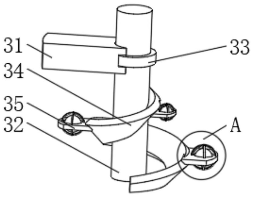
[0034] Sand crushing device 3, the sand crushing device 3 has a support rod 31, a sand crushing rod 32 is installed inside the storage tank 1, the top end of the sand crushing rod 32 extends to the outside of the material storage tank 1, and the outside of the sand crushing rod 32 The limit protruding ring 33 is installed, and the limit protruding ring 33 extends to the inside of the support bar 31 and is slidably connected with the support bar 31. The bottom end of the broken sand bar 32 is fixedly connected with a spiral plate 34, and the spiral plate 34 is away from the bottom of the broken sand bar 32. One side is fixedly connected with broken sand...

Embodiment 2

[0042] see Figure 1-5 , the present invention provides a technical solution: on the basis of Embodiment 1, an expansion slot 10 is evenly opened at the bottom of the storage tank 1, the expansion slot 10 runs through the storage tank 1, and the inner top of the expansion slot 10 is rotatably connected with an expansion board 11. One side of the expansion board 11 is symmetrically installed with sawtooth boards.

[0043] A return spring 12 is installed on one side of the expansion plate 11 , and the end of the return spring 12 away from the expansion plate 11 is fixedly connected with the storage barrel 1 .

[0044] The outer side of the storage tank 1 is provided with a storage tank 13, and the limit round rod 14 is fixedly connected between the two sides of the inner wall of the storage tank 13. The inner wall is fixedly connected, and the return spring 12 is slidably connected with the limit round rod 14.

[0045] One end of the return spring 12 away from the storage tank...


PUM


Abstract

The invention discloses a rail transit sanding system which comprises a material storage barrel, the top of the material storage barrel is designed to be open, a sanding opening is formed in the bottom of the material storage barrel, a sand crushing device is arranged in the material storage barrel, the sand crushing device is provided with a supporting rod, a sand crushing rod is installed in the material storage barrel, and one end of the top of the sand crushing rod extends out of the material storage barrel; a driving device is arranged in the material storage barrel and provided with a mounting plate, and the top of the mounting plate is fixedly connected with a driving motor; and a drying device arranged in the material storage barrel and provided with a drying groove, and the drying groove is formed in the top of a sand crushing transverse plate and penetrates through the sand crushing transverse plate. The invention relates to the technical field of rail transit. According to the rail transit sanding system, the purpose of crushing caked sprayed sand is achieved, the sanding stability is improved, the water content of the sprayed sand can be controlled, it is guaranteed that the water content of the sprayed sand is kept in a proper range, and the size of a sanding opening can be adjusted according to the sanding speed.

Description

technical field [0001] The invention relates to the technical field of rail transit, in particular to a rail transit sand spreading system. Background technique [0002] Railway transportation uses traction and brake adhesion friction generated by wheel-rail interaction to realize the operation of trains. With the construction of high-speed railways, the traction load of electric locomotives is increasing day by day. Improving the adhesion performance of locomotives has become a crucial issue. Sand spreading is the equipment of railway vehicles. The purpose is to use sand to increase the friction between the wheel and the rail, shorten the braking distance and increase the friction of climbing. [0003] However, the existing sanding device cannot crush the agglomerated sand, the stability of the sand is poor, the water content of the sand cannot be controlled, and the water content of the sand cannot be guaranteed to be maintained in an appropriate range. The speed of the s...

Claims


Application Information

Patent Timeline
IPC IPC(8): B61C15/10B02C19/22F26B5/16
CPCB61C15/10B02C19/22F26B5/16
Inventor 况雨昕
Owner CCCC MECHANICAL & ELECTRICAL ENG
Why Eureka
Try Eureka