Servo control lead screw transmission device and control method

A technology of servo control and transmission device, applied in the directions of aircraft transmission device, aircraft power device, aircraft power transmission, etc., can solve the problems of influence, increase in the size of the servo control transmission structure, increase the size of the servo motor, etc., to achieve high detection accuracy, The effect of reducing the failure of the transmission device and simplifying the structure

Active Publication Date: 2021-11-12
BEIJING MECHANICAL EQUIP INST
View PDF5 Cites 1 Cited by
  • Summary
  • Abstract
  • Description
  • Claims
  • Application Information

AI Technical Summary

Problems solved by technology

[0004] At present, the aforementioned servo control lead screw transmission mechanism still uses an angle sensor to detect the position of the motor, and the reliability of the angle sensor directly affects its safety; in addition, the structure of the angle sensor also increases the size of the servo motor, making the entire servo control transmission structure The size increase

Method used


Image

  • Servo control lead screw transmission device and control method
  • Servo control lead screw transmission device and control method
  • Servo control lead screw transmission device and control method

Examples


Embodiment Construction

[0047] Preferred embodiments of the present invention will be described in detail below in conjunction with the accompanying drawings, wherein the accompanying drawings constitute a part of the application and together with the embodiments of the present invention are used to explain the principle of the present invention and are not intended to limit the scope of the present invention.

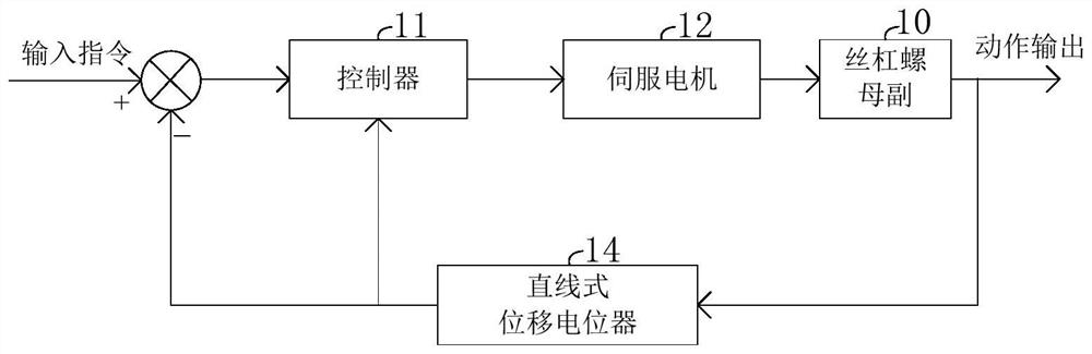
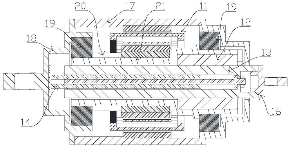
[0048] The embodiment of this specification provides a servo control transmission device. figure 2 It is a schematic structural diagram of the servo control lead screw 13 transmission device provided by the embodiment, image 3 It is a schematic cross-sectional view of some components of the servo control transmission. like figure 2 and image 3 As shown, in the present embodiment, the servo control lead screw 13 transmission device includes a servo motor 11, a lead screw nut 12 lead screw nut pair 10, a linear displacement potentiometer 14 and a controller 15; the lead screw nut pair 10 ...


PUM


Abstract

The invention provides a servo control lead screw transmission device and a control method. The transmission device comprises a servo motor, a lead screw nut pair, a linear displacement type potentiometer and a controller. The lead screw nut pair comprises a lead screw nut and a lead screw; the servo motor is used for driving the lead screw nut to rotate and the lead screw to translate relative to the lead screw nut; the linear displacement type potentiometer is used for generating a feedback signal representing the current position of the lead screw; and the controller is used for determining the current position of the lead screw and the current rotating position of the servo motor according to the feedback signal, and generating a control signal for controlling the servo motor to rotate according to the current position, the current rotating position and the input instruction. According to the servo control lead screw transmission device provided by the invention, the current position of the lead screw and the current rotating position of the servo motor are determined only by using the linear displacement type potentiometer, a special angle detection sensor does not need to be arranged in the servo motor, the structure is simplified, and transmission device faults caused by problems of the angle sensor are also reduced.

Description

technical field [0001] The invention relates to the technical field of mechanical automation, in particular to a servo-controlled screw drive mechanism. Background technique [0002] The servo-controlled screw drive mechanism is widely used in occasions where precise control of equipment movements is required, and the typical application is the steering gear of various aircraft. [0003] figure 1 It is a schematic diagram of a typical servo-controlled screw drive mechanism. like figure 1 As shown, a typical servo-controlled screw drive mechanism includes a controller 01, a servo motor 02, a screw nut pair 03 and a displacement sensor 04, and the servo motor 02 also includes an angle sensor. After the servo controller 01 receives the input command, it determines the current angular position of the servo motor 02 through the angle sensor and the protruding position of the screw in the screw nut pair determined by the position sensor 04 to generate a control signal to contro...

Claims


Application Information

Patent Timeline
Patent Type & Authority Applications(China)
IPC IPC(8): B64C13/30B64C13/34
CPCB64C13/30B64C13/34
Inventor 匡晓霖唐旭东郭威余东东王凯张程煜
Owner BEIJING MECHANICAL EQUIP INST
Why Eureka
Try Eureka