
Steel pipe mounting base and mounting method

A technology for installing bases and steel pipes, which is applied to building components, building insulation materials, earthquake resistance, etc., can solve problems such as low construction efficiency and damage, and achieve the effect of convenient construction, high efficiency, and strengthened constraints

Pending Publication Date: 2021-11-12
ZHEJIANG YASHA DECORATION
View PDF1 Cites 0 Cited by
  • Summary
  • Abstract
  • Description
  • Claims
  • Application Information

AI Technical Summary

Problems solved by technology

[0004] The present invention aims to overcome the problems in the above-mentioned prior art that when fixing the vertical steel pipe, the steel member will be damaged to a certain extent, at the same time, there are high requirements for the quality and accuracy of the opening, and the construction efficiency is low, etc., and it provides a steel pipe installation base and Installation method, convenient construction and high efficiency; material saving; avoiding damage to the main body of the building and steel components

Method used


Image

  • Steel pipe mounting base and mounting method
  • Steel pipe mounting base and mounting method
  • Steel pipe mounting base and mounting method

Examples


Embodiment 1

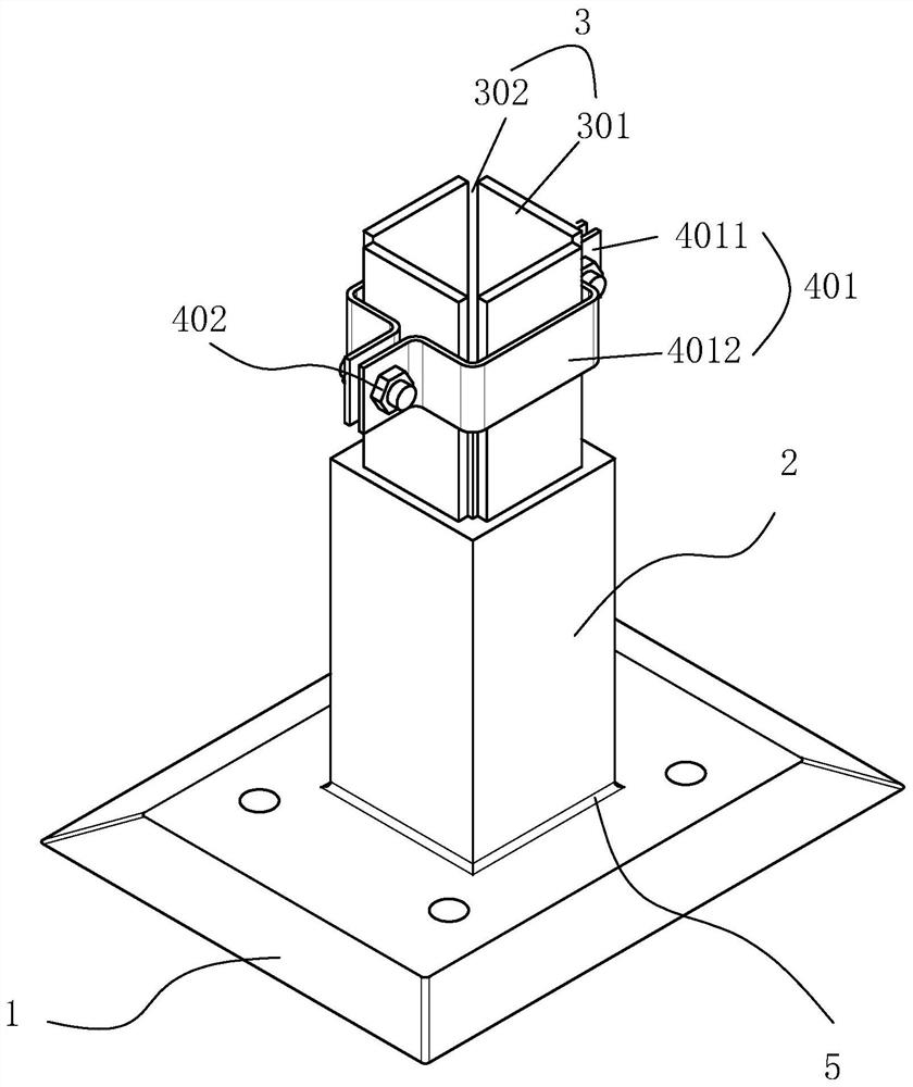
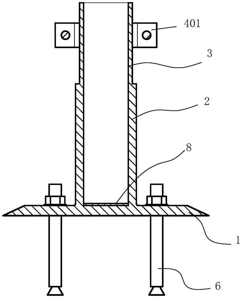
[0035] Such as figure 1 , figure 2 In the shown embodiment 1, a steel pipe installation base includes an integrated chassis 1 and a vertical pipe 2, the vertical pipe 2 is arranged perpendicular to the chassis 1, the steel pipe 7 is inserted into the vertical pipe 2, and the vertical pipe 2 is far away from the The upper end of the chassis 1 is provided with a limit guide structure 3, the limit guide structure 3 includes a number of limit pieces 301 uniformly arranged along the circumferential direction of the upper end surface of the standpipe 2, there are gaps 302 between adjacent limit pieces 301, the limit The guide structure 3 also includes a hoop assembly for reinforcing the steel pipe 7. The hoop assembly includes a pair of reinforcement plates 401 and a fixing piece 402 for fixing the two reinforcement plates 401. Here, the fixing piece 402 is a bolt structure.

[0036] In this technical solution, the chassis 1 is used to fix the ground, and the vertical pipe 2 is us...

Embodiment 2

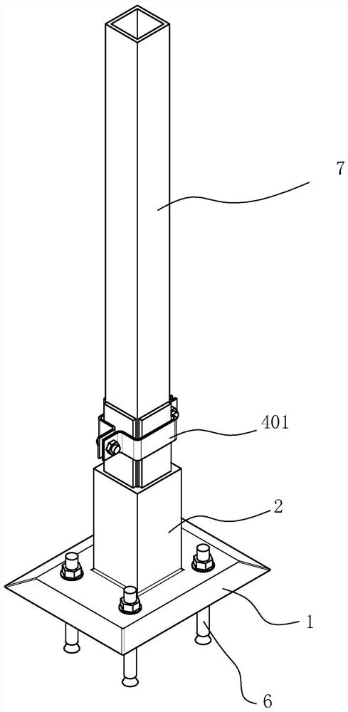
[0043] Such as image 3 As shown, embodiment 2 is a steel pipe installation method in which steel pipes are installed using the steel pipe installation base, comprising the following steps:

[0044] Step 1: Position and set out the chassis 1, and then fix the steel pipe installation base on the ground with expansion screws 6;

[0045] Step 2: Insert the steel pipe into the vertical pipe 2 and fix it once;

[0046] Step 3: Use the hoop assembly to constrain and fix the steel pipe to complete the connection between the steel pipe and the ground.

[0047] In this installation method, the installation base is positioned and laid out and then fixed by Pang Zhang screws, the assembly speed is fast, the steel pipe is directly inserted into the vertical pipe 2 and fixed by the hoop assembly, which will not cause damage to the steel pipe itself, and The fixing is firm to ensure the connection rigidity of the steel pipe.


PUM


Abstract

The invention discloses a steel pipe mounting base and a mounting method. The steel pipe mounting base comprises a base plate used for supporting and a vertical pipe used for fixing a steel pipe, and the base plate and the vertical pipe are integrally arranged. The steel pipe mounting method comprises the following steps that firstly, positioning and paying off are conducted on the base plate, and then the steel pipe mounting base is fixed to the ground through expansion screws; secondly, steel pipes are inserted into vertical pipes, and primary fixing is carried out; and thirdly, the steel pipe is restrained and fixed through a hoop assembly, and connection between the steel pipe and the ground is completed. According to the steel pipe mounting base and the mounting method, construction is convenient and fast, and the efficiency is high; materials are saved; and damage to a building main body and a steel member is avoided.

Description

technical field [0001] The invention relates to the field of architectural decoration, in particular to a steel pipe installation base and an installation method thereof. Background technique [0002] In the components such as partition walls and roof trusses, especially those used in public buildings, steel tube components are usually used, and the vertical steel tubes are the components that mainly bear the vertical force in the steel frame. Generally, vertical steel pipes are usually used to weld the slabs connected to the ground during on-site operations, but this method has very high technical requirements, and the construction quality of welding determines the quality of components to a large extent. At the same time, welding itself will cause certain damage to steel components. ; If the steel pipe is drilled and connected to the main body of the building with angle steel and bolts, there are great requirements for on-site positioning and measurement conditions, as wel...

Claims


Application Information

Patent Timeline
Patent Type & Authority Applications(China)
IPC IPC(8): E04B1/24E04B1/58E04B1/98E04B1/64
CPCE04B1/2403E04B1/98E04B1/644E04B2001/2421E04B2001/2463E04B2001/2451E04B2001/2418
Inventor 丁欣欣丁泽成周东珊文博蔡帅帅陈奕阊
Owner ZHEJIANG YASHA DECORATION
Learn More