Battery row, battery pack and manufacturing methods of battery row and battery pack

A manufacturing method and battery row technology, which is applied to battery pack parts, circuits, electrical components, etc., can solve the problems of small laser energy concentration points, damage, and failure to meet reliable electrical connections, and achieve good contact resistance consistency and high The effect of electrical connection stability

Active Publication Date: 2021-11-12
JIAXING MODULE BONDING TECH CO LTD
View PDF5 Cites 2 Cited by
  • Summary
  • Abstract
  • Description
  • Claims
  • Application Information

AI Technical Summary

Problems solved by technology

However, the energy concentration point of the laser is small, and the flatness requirements for multi-battery poles on the same plane are high during welding, otherwise it is easy to cause insufficient welding or over-welding (battery shell damage)
Since there is a certain tolerance in the height of the crimping connection between the top cover of the cylindrical battery and the shell, there is a certain tolerance in the height between the top pole and the shell pole at the bottom of the shell. After aligning one pole and fixing the structure by the bus bar, another The poles on one side are difficult to realign
If the laser welding process continues to be used on the other side, the welding yield will be greatly reduced (about 70%), which cannot meet the needs of reliable electrical connections on both sides, and it is difficult to promote the method of welding on both sides with laser welding.
[0004] Due to the above-mentioned problem of heat welding that is difficult to balance the efficiency and yield rate, in the process of forming cylindrical batteries, it has become a fast and reliable process implementation method to find electrical connections such as positive parallel connection, negative parallel connection and row-to-row series connection. Research Direction of Grouped Electrical Connection of Multi-Battery Arrays

Method used


Image

  • Battery row, battery pack and manufacturing methods of battery row and battery pack
  • Battery row, battery pack and manufacturing methods of battery row and battery pack
  • Battery row, battery pack and manufacturing methods of battery row and battery pack

Examples


Embodiment 1

[0074] This Example 1 provides a composite electrical connector battery discharge process, for a cylindrical battery prepared as a single row within the rows in parallel and in series between the CTP module, particularly suitable for the preparation of new energy vehicle power battery cell, and the same applies to the low-speed electric vehicles, electric bicycles and other storage products.

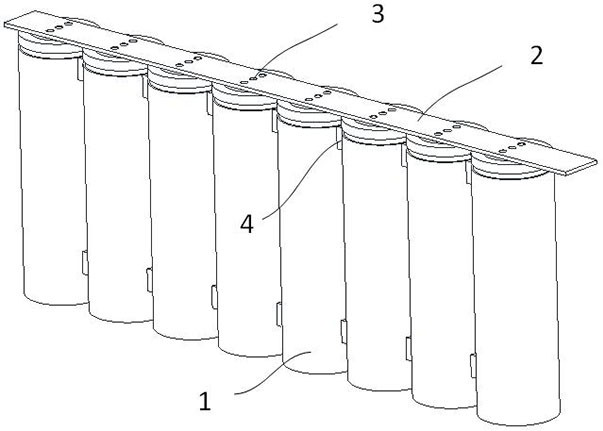
[0075] according to Figure 1 - Figure 3 A battery discharge embodiment of the present embodiment, i.e., a composite electrically connected to the battery discharge process, the battery is one row of the base unit power battery module, comprising:

[0076] A plurality of single cylindrical battery 1, a plurality of cylindrical cells 1 are arranged in single rows; single cylindrical cell 1 includes a top pole and the pole housing side; top pole is made of a conductive metal material; battery discharge All single cylindrical cells 1 are arranged in the same direction;

[0077] 2 busbar made of ...

Embodiment 2

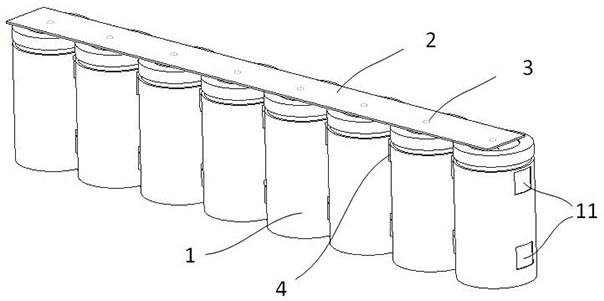
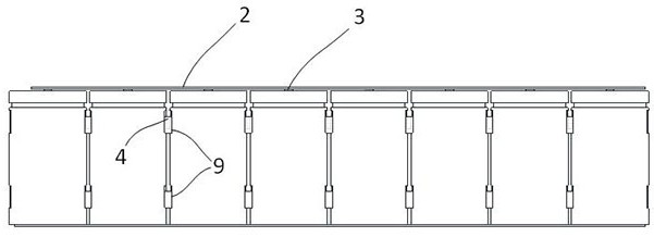
[0089] This Example 2 provides a composite electrically connected to the battery discharge process, the structure mainly different from Embodiment 2 in the busbar 1. according to Figure 4 - Figure 5 , Disposed on the bus bar 2 comprises a bent end portion 21 of the bus, the bus bent portion 21 positioned outside both ends of the battery discharge. Bending both end portions of the bus 21 may have, it may be present only at one end 2 of the bus bar.

[0090] The bent portion 21 of the bus functions include but are not limited to assume the function of electrically connecting the battery to the other row corresponds to the external top side opposite pole. The bent portion of the bus 21 further includes functions to constrain the longitudinal gap discharge the battery to a certain extent.

[0091] Preferably, the Figure 5 , With a distance between the single cylindrical battery 21 from the bent portion of the bus end portion of the side surface of the pole housing 1; monomer Preferabl...

Embodiment 3

[0093] according to Figure 6 - Figure 9 The present example provides a composite 3 is electrically connected to the battery technology, the above-described embodiments comprises a plurality of arrays arranged in a battery disclosed in any row, parallel rows inside the battery of the battery pack, the serial connection between adjacent cells in a row.

[0094] Battery pole row side of the housing at least partially outside of the housing as a pole of a battery discharge.

[0095] As a preferred embodiment, the housing further comprising a plurality of pole 7 bridge approach, Approach in each pole housing 7 are electrically connected to the side surface of housing a battery pole row.

[0096] Each row of the battery pole busbar outer housing sequentially with the neighboring rows of cells 2 are electrically connected in series between adjacent cells in a row; first busbar cell 2 as a top row of the external pole of the battery pack.

[0097] As a preferred embodiment, the adjacent r...


PUM


Abstract

The invention relates to a battery row, a battery pack and manufacturing methods of the battery row and the battery pack. The battery row comprises: a plurality of single cylindrical batteries which are arranged in rows, wherein each single cylindrical battery comprises a top pole and a side shell pole, and all the single cylindrical batteries in the battery row are arranged in the same direction; and a busbar, which is arranged close to the top poles of the plurality of single cylindrical batteries, wherein the top pole of each single cylindrical battery is electrically connected with the busbar in a hot welding manner, at least one cold welding structure is arranged between the side shell poles of the adjacent single cylindrical batteries, and all the single cylindrical batteries in the battery row are of a parallel structure. According to the invention, a composite welding process is adopted, a hot welding process is adopted for the top pole of each single cylindrical battery and the busbar, so all welding spots are manufactured with extremely high efficiency; and a cold welding process is adopted for the side shell poles of every two adjacent single cylindrical batteries, so the electric connection of the shell poles is efficiently completed.

Description

Technical field [0001] The present invention relates to the field of new energy power cells, and more particularly to a battery row, a battery pack, and a manufacturing method thereof. Background technique [0002] With the continuous development of the new energy industry, the market demand in the power battery module is expanding, which has put forward higher requirements for the production efficiency of the power battery module. [0003] The process of grouping multiple monomer cylindrical batteries is one of the main technical branches of the power battery module. Cylindrical battery pack string parallel electrical connection process, usually the top pole column is parallel and the housing pole column is in parallel with the same electrical connection process, and the industry typically uses a bus welding and battery pole metal metal welding. Among them, the heat welding is usually spot welding, laser welding and ultrasonic welding. Among them, spot welding and ultrasonic wel...

Claims


Application Information

Patent Timeline
Patent Type & Authority Applications(China)
IPC IPC(8): H01M50/516H01M50/507H01M50/509H01M50/258H01M50/213
CPCH01M50/516H01M50/507H01M50/509H01M50/258H01M50/213Y02E60/10
Inventor 汪波刘存良杨钢
Owner JIAXING MODULE BONDING TECH CO LTD
Why Eureka
Try Eureka