Balloon catheter

A technology of balloon catheters and balloons, which is applied in the direction of balloon-shaped catheters and catheters, which can solve the problems of damaged balloons and scoring components, easy enlargement of the outer diameter, and difficulty in containing them, and achieve the effect of not being easy to expand

Active Publication Date: 2021-11-12
KANEKA CORP
View PDF19 Cites 0 Cited by
  • Summary
  • Abstract
  • Description
  • Claims
  • Application Information

AI Technical Summary

Problems solved by technology

Similarly, balloon catheters equipped with scoring elements such as those in Patent Documents 1 to 6 can be considered to cover the protective tube on the balloon. However, in this case, it is clear that the following problems arise. In the previous air leak test of the balloon, due to the large gap between the balloon and the protective tube, the balloon inflated in the protective tube, and when the balloon catheter was used, the balloon expanded However, the outer diameter tends to become larger, and the passage of the balloon catheter in the blood vessel becomes poor.
In addition, when the inner diameter of the protective tube is reduced in order to reduce the gap between the balloon and the protective tube, it is confirmed that the problem that the balloon is accommodated in the inner cavity of the protective tube becomes difficult, and the balloon Capsule, scoring element damage

Method used


Image

  • Balloon catheter
  • Balloon catheter
  • Balloon catheter

Examples


Embodiment Construction

[0041] Hereinafter, based on the following embodiments, the present invention will be described in more detail. Of course, the present invention is not limited by the following embodiments, and of course, it can be appropriately changed within the scope of meeting the aforementioned and hereinafter described gist. Implementation, these are included in the technical scope of the present invention. In addition, in each drawing, hatching, member reference numerals, etc. may be omitted for convenience, and in this case, refer to the specification and other drawings. In addition, in order to facilitate understanding of the characteristics of the present invention first, the dimensions of various components in the drawings may differ from actual dimensions.

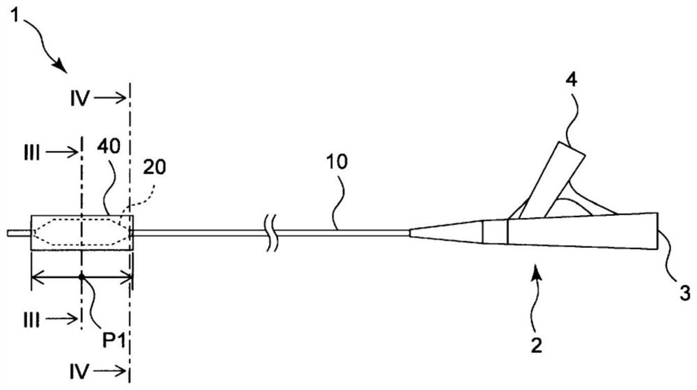
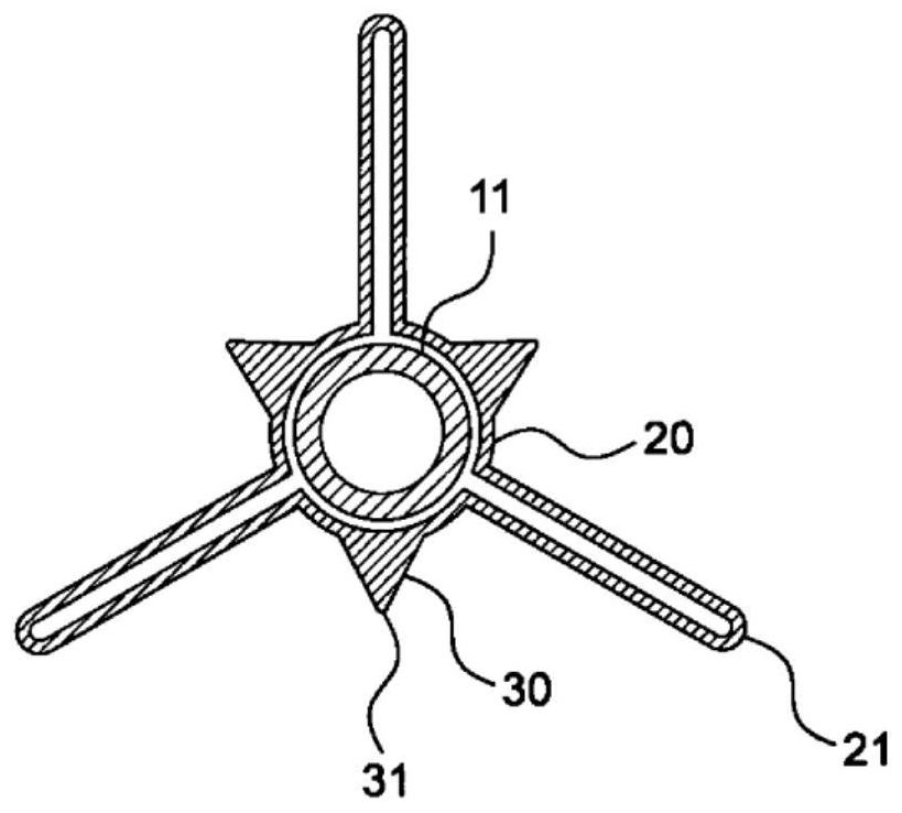
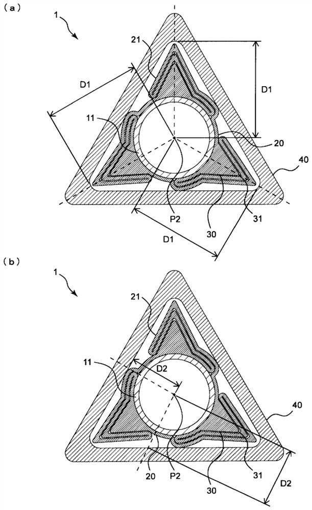
[0042] figure 1 An overall view showing the balloon catheter 1 in the embodiment of the present invention, figure 2 A cross-sectional view perpendicular to the far-near direction of the balloon 20 in a deflated state is show...


PUM


Abstract

Provided is a balloon catheter, wherein while a balloon that has protruding sections is housed in a lumen of a protective tube, the balloon does not readily expand within the protective tube during an air leak test of the balloon. The balloon catheter (1) has a shaft that extends in distal / proximal direction; a balloon (20) that is provided to a distal side of the shaft, and in a contracted state has a plurality of vane-shaped sections (21); protruding sections (30) that are provided to an outside surface of the balloon (20); and a protective tube (40), wherein the balloon (20) is positioned in a lumen thereof, and in a cross-section that is perpendicular to the distal / proximal direction and is at the midpoint of the distal / proximal direction length of the protective tube (40), the distance (D1) from the centroid (P2) of the protective tube (40) to an inner surface of the protective tube (40) while passing through a top section (31) of a protruding section (30) is longer than the distance (D2), in the interval between a protruding section (30) and a neighboring protruding section (30), from the centroid (P2) of the protective tube (40) to the inner surface of the protective tube (40) without passing through a protruding section (30).

Description

technical field [0001] The present invention relates to a balloon catheter with a protective tube. Background technique [0002] It is known that various diseases occur due to narrowing of blood vessels, which are channels for blood to circulate in the body, stagnation of blood circulation. In particular, narrowing of the coronary arteries that supply blood to the heart may cause serious diseases such as angina pectoris and myocardial infarction. As a method for treating such stenotic portions of blood vessels, there are angioplasty such as PTA and PTCA, which use a balloon catheter to dilate the stenotic portion. Angioplasty is a minimally invasive treatment that does not require open-chest surgery such as heart bypass surgery, and is widely performed. [0003] On the inner wall of a blood vessel, a hardened narrow portion may be formed due to calcification or the like. In such calcified lesions, it is difficult for general balloon catheters to expand the sclerotic steno...

Claims


Application Information

Patent Timeline
Patent Type & Authority Applications(China)
IPC IPC(8): A61M25/10
CPCA61M25/1002A61M25/104A61M2025/1004A61M2025/1081A61M2025/109A61M2025/1086
Inventor 古贺阳二郎小嶋真弘中野良纪杖田昌人大角真太郎
Owner KANEKA CORP
Why Eureka
Try Eureka