A shuttlecock serve electric machine

An electric and shuttlecock technology, applied in the direction of racket, sports accessories, etc., can solve the problem of needing others to cooperate to feed the shuttlecock, and achieve the effect of improving practicability and efficiency

Active Publication Date: 2022-05-17
CHONGQING TECH & BUSINESS UNIV
View PDF0 Cites 0 Cited by
  • Summary
  • Abstract
  • Description
  • Claims
  • Application Information

AI Technical Summary

Problems solved by technology

[0004] In view of the above situation, in order to overcome the defects of the prior art, the present invention provides a shuttlecock serving electric machine, which effectively solves the problem that others need to cooperate to feed the shuttlecock when practicing shuttlecock kicking

Method used


Image

  • A shuttlecock serve electric machine
  • A shuttlecock serve electric machine
  • A shuttlecock serve electric machine

Examples


Embodiment 1

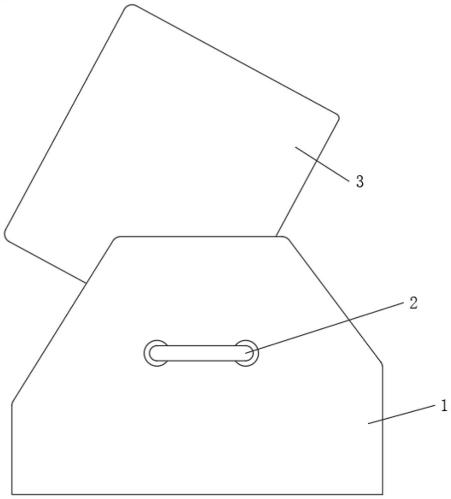
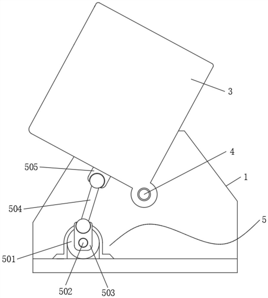
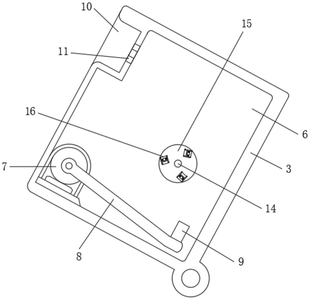
[0039] Embodiment one, by Figure 1 to Figure 7 Given, the present invention comprises a U-shaped base 1, handles 2 are installed at both ends of the U-shaped base 1, a rectangular housing 3 is installed inside the U-shaped base 1, and the rectangular housing 3 is connected to the U-shaped housing through a connecting shaft 4. U-shaped base 1 is rotatably connected, through the setting of connecting shaft 4, the rectangular housing 3 can be effectively rotatably adjusted, and an angle adjustment assembly 5 is installed between the rectangular housing 3 and the bottom of the inner side of the U-shaped base 1, U The inside of one side of the shaped base 1 is provided with a first cavity 6, the bottom of the first cavity 6 is equipped with a stepping motor 7, and the output end of the stepping motor 7 is fixedly equipped with a rotating rod 8, and the stepping motor 7 and the rotation The rod 8 is installed obliquely at the bottom of the first cavity 6, so that one of the transmi...

Embodiment 2

[0053] Embodiment two, on the basis of embodiment one, by figure 2 Given, the angle adjustment assembly 5 includes a double output shaft motor 501, the double output shaft motor 501 is installed on the bottom of the inner side of the U-shaped base 1, and both ends of the double output shaft motor 501 are equipped with threaded rods 502, two threaded rods The surface of 502 is all screwed with moving block 503, and the top of two moving blocks 503 is all equipped with connecting rod 504, and one end of two connecting rods 504 is all installed with fixed block 505, and two fixed blocks 505 are all connected with rectangular housing 3 connected, so that the angle of the rectangular housing 3 can be effectively adjusted;

[0054] Both the opposite ends of the moving block 503 and the fixed block 505 are provided with circular grooves, the insides of the two circular grooves are rotated and clamped with balls, and the connecting rod 504 is fixedly connected between the two balls; ...

Embodiment 3

[0056] Embodiment three, on the basis of embodiment one, by image 3 and Figure 5 Given, the shuttlecock transmission long groove 17 communicates with the shuttlecock placement groove 10, and the communicating long groove 18 communicates with the percussion opening 11, thereby effectively transporting the shuttlecock;

[0057] Both sides of the bottom of the shuttlecock transmission long groove 17 are provided with grooves, and rollers are installed equidistantly inside the grooves, so that the placed shuttlecocks can move effectively;

[0058] When the shuttlecock is placed in the inside of the shuttlecock transmission long slot 17, the shuttlecock will be placed between the two toggle levers 22, so that the rotation of the toggle lever 22 can effectively stir the shuttlecock to move, so that the shuttlecock moves to The shuttlecock is placed inside the slot 10, and the shuttlecock moves more conveniently and stably through the rolling of the roller.


PUM


Abstract

The invention relates to the technical field of sports equipment, and discloses a shuttlecock serving electric machine, which solves the problem that other people need to cooperate with feeding the shuttlecock to practice shuttlecock kicking. It includes a U-shaped base, and the two ends of the U-shaped base are installed There is a handle, a rectangular shell is installed inside the U-shaped base, the rectangular shell is rotatably connected to the U-shaped base through a connecting shaft, and an angle adjustment component is installed between the rectangular shell and the bottom inside the U-shaped base, U The inside of one side of the shaped base is provided with a first cavity, the bottom of the first cavity is equipped with a stepping motor, the output end of the stepping motor is fixedly installed with a rotating rod, and one end of the rotating rod is fixedly installed with a top block; The ball-serving electric machine can effectively meet the needs of shuttlecock feeding for practicing shuttlecock kicking. At the same time, the shuttlecock-serving electric machine can adjust the feeding angle of the shuttlecock, and the shuttlecock-serving electric machine has the function of automatically feeding the shuttlecock.

Description

technical field [0001] The invention belongs to the technical field of sports equipment, in particular to a shuttlecock serving electric machine. Background technique [0002] Shuttlecock kicking, also known as shuttlecock, is a simple and easy fitness exercise. It is widely spread in China and has a long history. It is a traditional folk sports activity. Regularly performing this activity can exercise muscles and bones to promote health; kicking shuttlecock is A good whole-body sport that is not limited by the venue, personnel, or age. In recent years, shuttlecock kicking is no longer simply kicking back and forth with the soles of the feet, but innovations in forms and patterns are constantly appearing, such as Some high-difficulty and high-skill movements such as shuttlecock kicking and scissor kick in kicking or round kicking are very entertaining. [0003] If you want to kick the shuttlecock well, you must often practice to improve the shuttlecock kicking technique, bu...

Claims


Application Information

Patent Timeline
Patent Type & Authority Patents(China)
IPC IPC(8): A63B69/40A63B102/10
CPCA63B69/40A63B2102/10
Inventor 曾文瑶
Owner CHONGQING TECH & BUSINESS UNIV
Why Eureka
Try Eureka