Rainwater rapid drainage system

A rainwater and fast technology, applied in waterway systems, sewer systems, water supply devices, etc., can solve problems such as slowing water flow velocity, reducing water flow energy, affecting the drainage efficiency of siphon rainwater drainage systems, and improving drainage efficiency. diversion effect

Active Publication Date: 2021-11-16
KESHUN WATERPROOF TECH CO LTD
View PDF12 Cites 0 Cited by
  • Summary
  • Abstract
  • Description
  • Claims
  • Application Information

AI Technical Summary

Problems solved by technology

The kinetic energy of the water flow is greatly reduced, and the flow rate of the water flow out of the gutter joint becomes slower, thereby affecting the drainage efficiency of the siphon rainwater drainage system

Method used


Image

  • Rainwater rapid drainage system
  • Rainwater rapid drainage system
  • Rainwater rapid drainage system

Examples


Embodiment 1

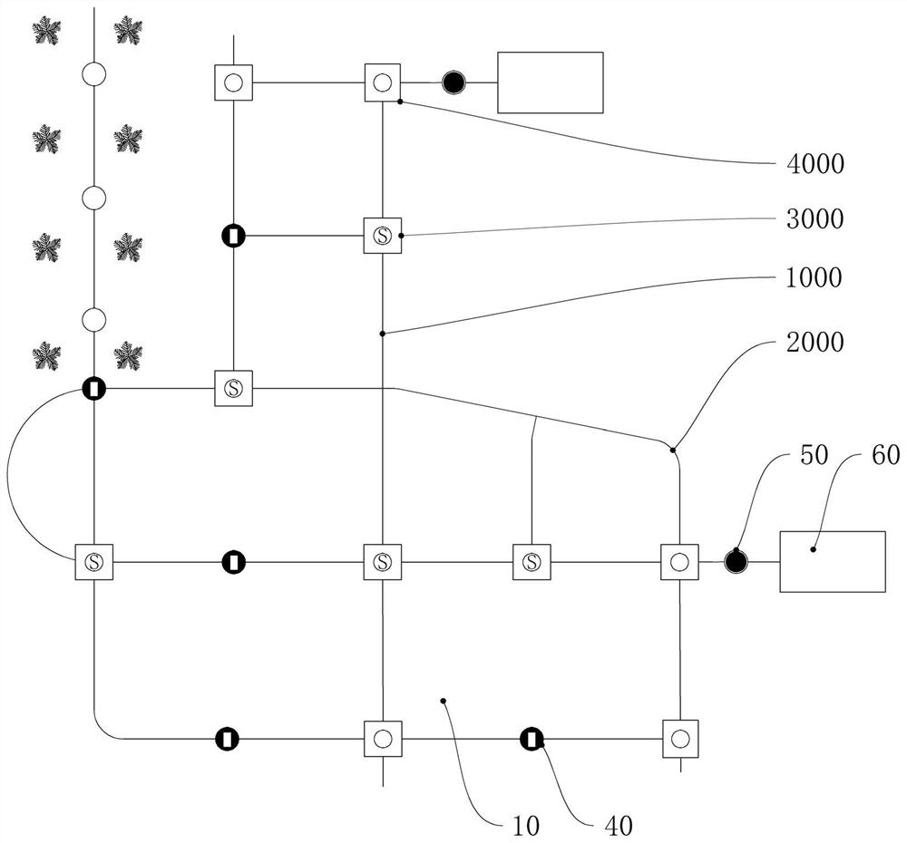
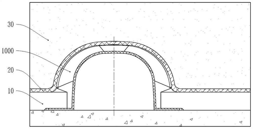
[0076] Such as figure 1 As shown, this embodiment is a rainwater rapid drainage system, including a drainage board 10, a drainage network and a water-permeable layer covering the drainage network. The drainage network includes at least a unit area: distributed around the unit area through drainage Several siphon flow diverter devices 4000 connected to the water tank, siphon flow diverter devices 4000 discharge water outside the unit area; several variable flow drainage devices 3000 distributed on the nodes of the drainage network in the unit area, variable flow drainage devices The device 3000 is connected to one or more siphon deflectors 4000 through drainage grooves, and guides the water at different positions in the unit area to the suction deflectors; the drainage boards 10 are distributed between the drainage grooves to undertake the unit area The water infiltrated through the water-permeable layer is introduced into the drainage tank.

[0077] The rainwater rapid draina...

Embodiment 2

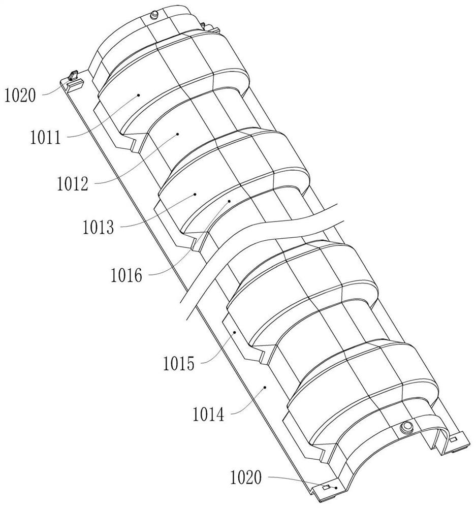
[0086] Such as Figure 2-2 , 2-3 , 2-4, this embodiment is a straight-through drainage tank 1000, including a tank body 1011, a bottom plate 1014, a water inlet 1015 and a buckle structure 1020, the opening of the tank body 1011 is downward, and the bottom plate 1014 is horizontally arranged on the tank body On both sides of the opening of 1011 , buckle structures 1020 are provided at both ends of the slot body 1011 in the longitudinal direction. The groove body 1011 is provided with protruding parts 1013 at intervals, and between two adjacent protruding parts 1013 is a non-protruding part 1012. It is an arched bulge connecting the bottom plates 1014 on both sides.

[0087] The protrusion 1013 has a certain length along the longitudinal direction of the tank body 1011 . The surfaces of the protruding portion 1013 and the non-protruding portion 1012 are smooth, and the entire tank body 1011 has no outward sharp ribs, which ensures that the geotextile is not cut. The protrud...

Embodiment 3

[0103] Such as Figure 3-1 , 3-2 As shown, the present embodiment is a kind of flexible drain tank 2000, including several drain tank units 2010, and the two ends of each drain tank unit 2010 are provided with connecting structures 2031; the drain tank units 2010 are connected to each other through the connecting structures 2031, and can rotate with each other; several drainage tank units 2010 are connected one by one in sequence to form the flexible drainage tank 2000 .

[0104] In this embodiment, the traditional straight-through drainage tank is divided into several drainage tank units 2010 through bionic design. Both ends of each drainage channel unit 2010 are provided with connection structures 2031 , and several drainage channel units 2010 are connected in sequence, and then assembled into a flexible drainage channel 2000 . Both ends of the flexible drainage groove 2000 can be connected with the above-mentioned straight drainage groove 1000 . On the one hand, since an...


PUM


Abstract

The invention relates to the field of drainage, in particular to a rainwater rapid drainage system capable of rapidly draining rainwater. The rainwater rapid drainage system comprises drainage plates, a drainage network and a permeable layer covering the drainage network, the drainage network at least comprises unit areas, a plurality of siphon flow changing devices, a plurality of flow changing drainage devices. The multiple siphon flow changing devices are distributed on the periphery of a unit area and connected through drainage grooves, a siphon flow changing device discharges water out of the unit area; the flow changing drainage devices are distributed on nodes of the drainage network in the unit areas, and the flow changing drainage devices are connected with one or more siphon flow changing devices through the drainage grooves to directionally guide the water at different positions in the unit areas to the suction flow changing devices; and the drainage plates are distributed among the drainage grooves and used for receiving the water permeated from the permeable layer in the unit area and guiding the water into the drainage grooves. According to the rainwater rapid drainage system, by reasonably arranging the relation among a drainage plate, a drainage groove, a flow changing drainage device and a siphon flow changing device, the drainage efficiency is improved step by step, and an efficient drainage system is formed.

Description

technical field [0001] This patent relates to the field of drainage, more specifically, to a rainwater rapid drainage system. Background technique [0002] Sponge city refers to the fact that the city, like a sponge, has good resilience in adapting to environmental changes and dealing with natural disasters caused by rain. In order to realize the sponge city, the roof drainage system is widely used on the roof, especially the planted roof, which can collect the rainwater and irrigation water falling on the roof, and then discharge the rainwater into the ground through pipelines or store it in the underground reservoir. . The system is mainly composed of drainage boards laid on the roof, drainage grooves and drainage groove joints. The drainage grooves are connected into a network through the drainage groove joints and interwoven between the tiled drainage boards. After the roof drainage system is laid, it is usually covered with geotextiles and backfilled with green soil a...

Claims


Application Information

Patent Timeline
Patent Type & Authority Applications(China)
IPC IPC(8): E03F3/02E03F3/04E03F5/10
CPCE03F3/02E03F3/04E03F5/10Y02A20/108
Inventor 董海叶吉徐俊峰
Owner KESHUN WATERPROOF TECH CO LTD
Why Eureka
Try Eureka