
Wind power generation blade conveying device with stabilizing assembly

A technology for wind power blades and transportation devices, which is applied in the directions of wind turbine transportation and wind energy power generation, can solve the problems of inconvenient transportation, time-consuming and laborious, and blade shaking in production factories, and avoid difficult fixing, reduce safety risks, and reduce vibration forces. Effect

Active Publication Date: 2021-11-16
江苏久力风电技术开发有限公司
View PDF5 Cites 0 Cited by
  • Summary
  • Abstract
  • Description
  • Claims
  • Application Information

AI Technical Summary

Problems solved by technology

[0002] Wind power belongs to green energy, and it has developed rapidly in recent years, and the installed capacity across the country has increased year by year. After the blades used in wind power generation are produced, they are often inconvenient to transport in the production plant due to their huge blades.
[0003] In the prior art, after the blades are produced, when the blades are transported and loaded, an aerial crane is often required for transportation. Since the transportation of the aerial cranes is not convenient for controlling the direction and position of the blades, when loading the blades It is often very time-consuming and labor-intensive, and in the process of transporting and loading by the aerial crane, the blade will shake, and there is a risk of collision with other blades. Secondly, when the blade is transported and loaded, it often requires multiple people to assist, which has the advantages of Certain potential safety hazards, for this reason, we propose a wind power generation blade transportation device with stabilizing components

Method used


Image

  • Wind power generation blade conveying device with stabilizing assembly
  • Wind power generation blade conveying device with stabilizing assembly
  • Wind power generation blade conveying device with stabilizing assembly

Examples


Embodiment Construction

[0034] The technical solutions of the present invention will be clearly and completely described below with reference to the embodiments. Obviously, the described embodiments are only a part of the embodiments of the present invention, rather than all the embodiments. Based on the embodiments of the present invention, all other embodiments obtained by those of ordinary skill in the art without creative efforts shall fall within the protection scope of the present invention.

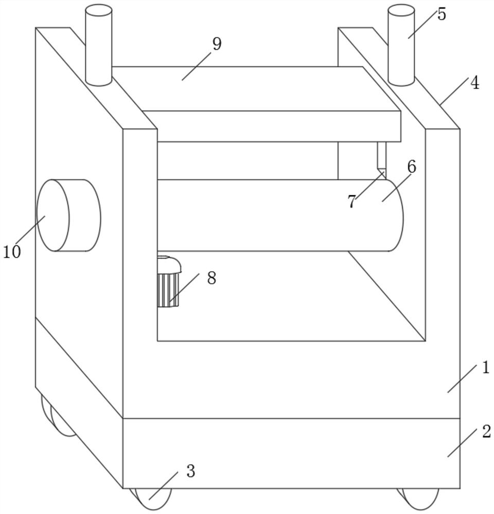
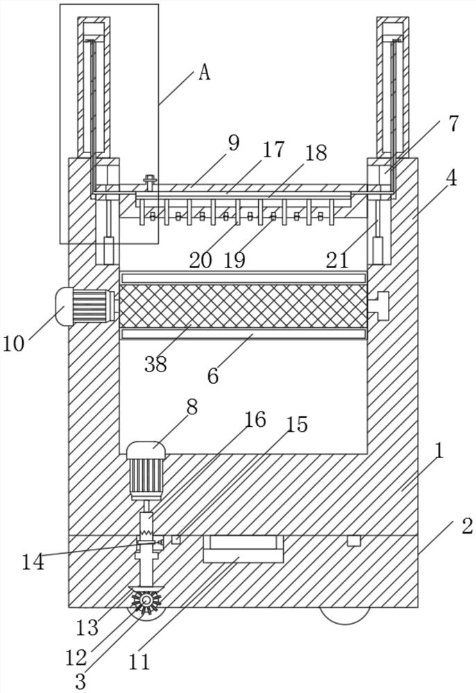
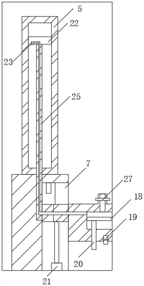
[0035] see Figure 1-8 As shown, a wind power blade transportation device with a stabilizing component includes a casing 1, and side plates 4 are fixedly connected to both sides of the top of the casing 1, and a sliding plate 9 is slidably installed between the two side plates 4. A roller column 38 is rotatably installed between the side plates 4. The roller column 38 is located directly below the slide plate 9. The interior of the slide plate 9 is provided with an empty slot 17. The bottom of the plate ...


PUM


Abstract

The invention relates to the field of wind power generation, and particularly discloses a wind power generation blade conveying device with a stabilizing assembly. The wind power generation blade conveying device comprises a shell, wherein side plates are fixedly connected to the two sides of the top of the shell; a sliding plate is arranged between the two side plates in a sliding mode; a roller column is rotationally arranged between the two side plates; the roller column is located right below the sliding plate; an empty groove is formed in the sliding plate; the empty groove communicates with an air inlet assembly; a baffle is connected in the empty groove in a sliding mode; and a plurality of clamping strips are fixedly connected to the bottom of the baffle. According to the wind power generation blade conveying device, the stability of blades can be effectively guaranteed, on the other hand, the force borne by a single device can be effectively shared, so that the stability of the device is guaranteed; and through the rotation of wheels, the direction of the blades can be effectively controlled, and the risk that the blades collide with other blades or objects when the blades are conveyed by using an aerial crane can be effectively avoided.

Description

technical field [0001] The invention relates to a transportation device, in particular to a wind power generation blade transportation device with a stabilizing component, belonging to the field of wind power generation. Background technique [0002] Wind power belongs to green energy. It has developed rapidly in recent years. The installed capacity of wind power has increased year by year. After the blades used for wind power generation are produced, they are often inconvenient to transport in production factories due to the huge blades. [0003] In the prior art, after the blades are produced, when the blades are transported and loaded into the truck, they often need to be transported by an aerial crane. Since the transportation of the blades by the aerial crane is inconvenient to control the direction and position of the blades, when loading the blades. It is often very time-consuming and labor-intensive, and in the process of transportation and loading by the aerial cran...

Claims


Application Information

Patent Timeline
Patent Type & Authority Applications(China)
IPC IPC(8): F03D13/40
CPCF03D13/40Y02E10/72
Inventor 潘恒伟
Owner 江苏久力风电技术开发有限公司
Learn More