Data migration method, host and solid-state storage device (SSD)

A host and data technology, applied in the storage field, can solve problems such as occupying the host, affecting the performance of the storage system, and affecting normal data access, so as to achieve the effect of guaranteeing speed and reducing performance impact

Pending Publication Date: 2021-11-16
HUAWEI TECH CO LTD
View PDF0 Cites 2 Cited by
  • Summary
  • Abstract
  • Description
  • Claims
  • Application Information

AI Technical Summary

Problems solved by technology

It can be seen that, in the prior art, when data migration is performed between SSDs, the transferred data must be controlled by the CPU of the host computer during the data transmission process, thus occupying the bandwidth of the CPU of the host computer, which will affect the normal operation of data in other SSDs. Accesses affect the performance of the entire storage system
In order to reduce the impact of data migration between SSDs on the performance of the storage system, the host CPU bandwidth occupied by data migration between SSDs is generally limited, which will lead to a long time for data migration between SSDs and increase the risk of data loss
In addition, even if the bandwidth of data migration between SSDs is limited, the performance of the storage system will still be affected.

Method used


Image

  • Data migration method, host and solid-state storage device (SSD)
  • Data migration method, host and solid-state storage device (SSD)
  • Data migration method, host and solid-state storage device (SSD)

Examples


no. 1 example

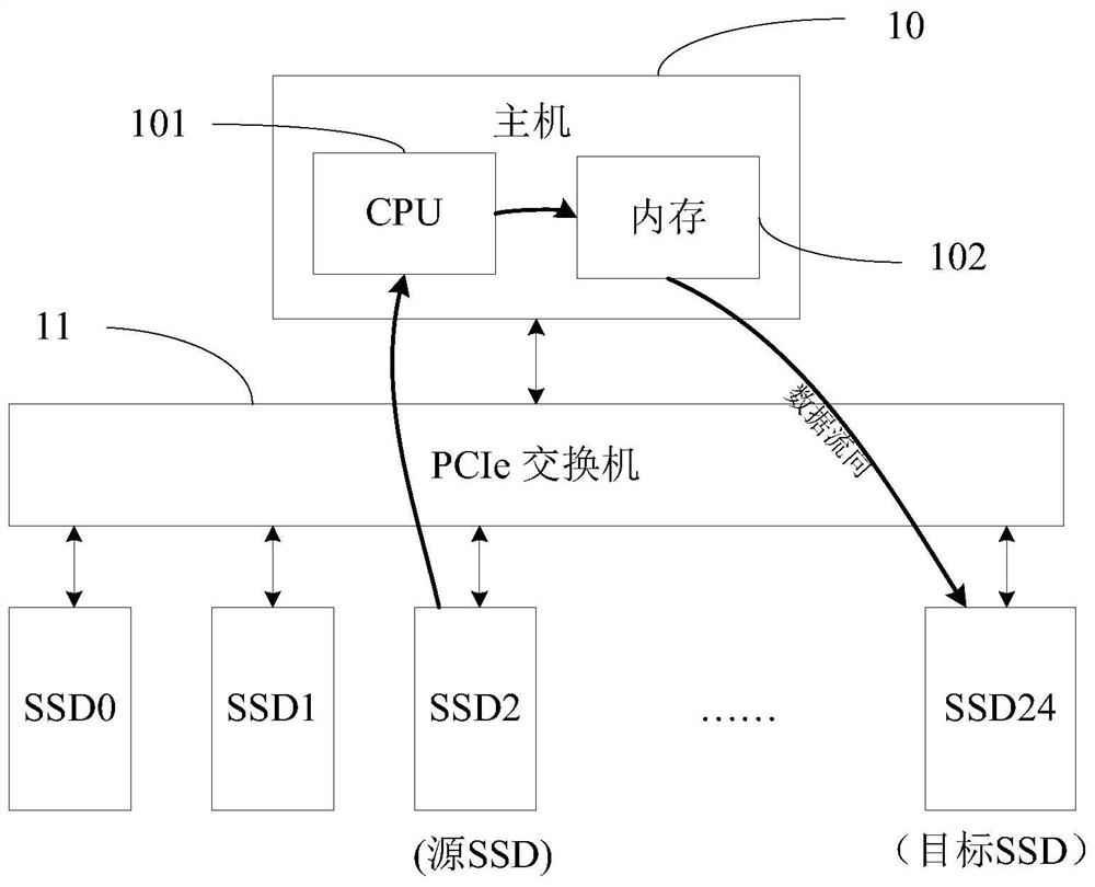
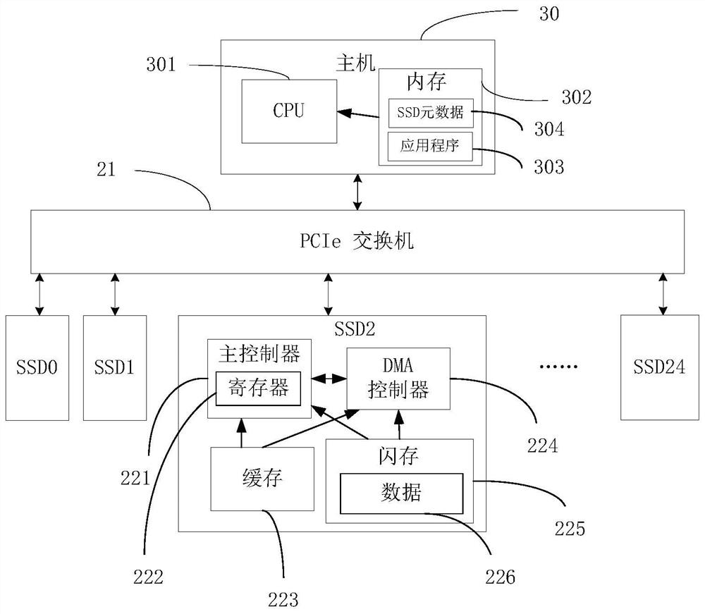
[0091] Such as image 3 Shown is a structural diagram of the storage system in the first embodiment of the present invention. The architecture diagram of the storage system in the first embodiment and figure 1 The architectures of the storage systems in the prior art are basically the same, including a host 30 , a PCIe switch 31 , and SSD0 to SSD24 , and the SSD1 to SSD24 are connected to each other through the PCIe switch 31 .

[0092] The host 30 includes a CPU 301 and a memory 302. The CPU 301 is used to run an application program 303 in the memory to implement some functions provided by the host 30, such as controlling data access and migration in SSD0-SSD24. The memory 302 also stores the metadata 304 of SSD0-SSD24, and the metadata 304 records the information of the data stored in each SSD, such as the data volume of the stored data, and the logical address information of the stored data Wait.

[0093] The structures of the SSD0-SSD24 are basically the same, and the s...

no. 2 example

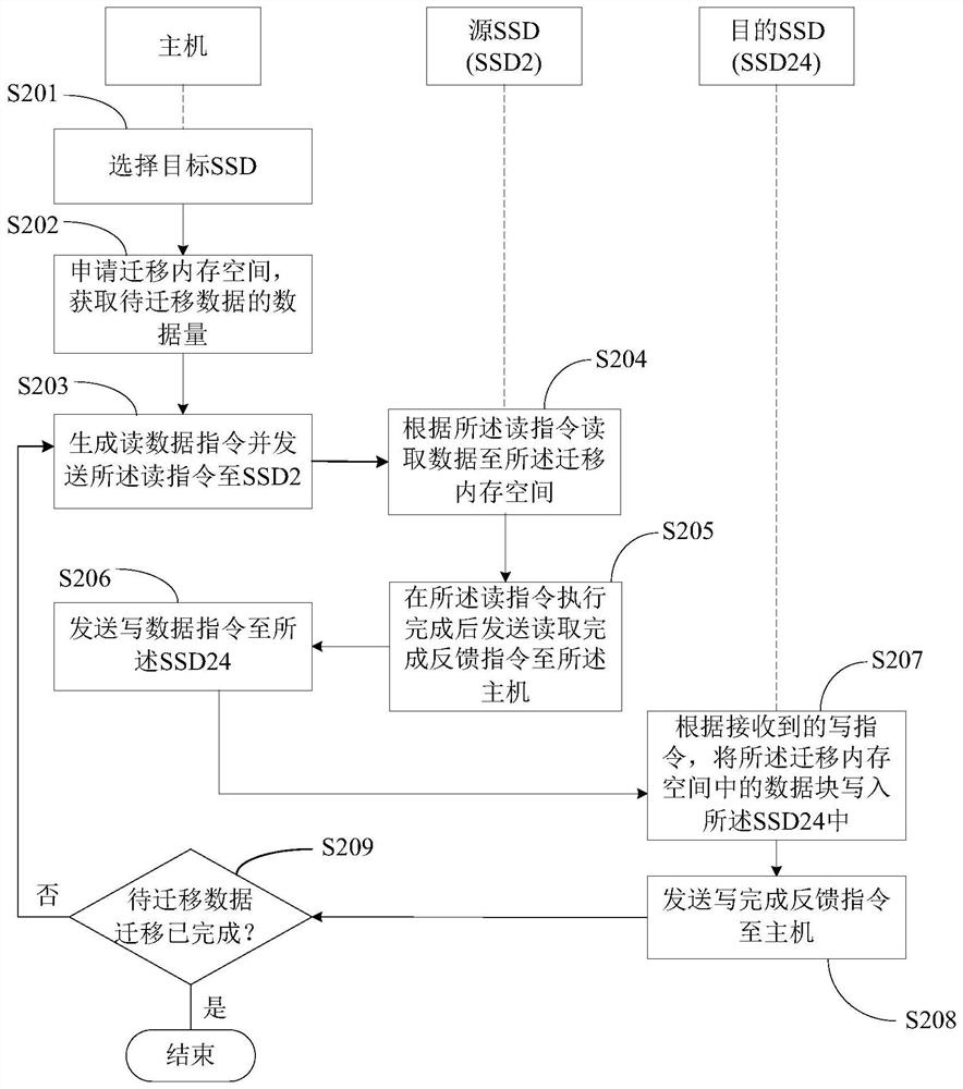
[0135] The only difference between the second embodiment and the first embodiment is that in the second embodiment, the data to be migrated in the source SSD is first read to the local migration cache, and then the data in the local migration cache is written to the target SSD . The data migration method in the second embodiment will be described below with reference to a flow chart.

[0136] In the second embodiment, the architecture of the storage system is the same as image 3 Similarly, the SSD in the storage system will also provide a cache for the host and other SSDs to access, so in the following description, it will still use image 3 The architecture of the second embodiment is described. In addition, the method for the SSD to provide cache for the host and other SSDs to access is the same as that in the first embodiment. For details, please refer to Figure 4 description and will not be repeated here.

[0137] The following will combine Figure 6 A method for mi...

no. 3 example

[0161] The difference between the third embodiment and the first embodiment is that in the third embodiment, when the host SSD detects that data in the source SSD needs to be migrated, it only needs to send a migration command to the source SSD, and the source SSD The migration command can migrate the data to be migrated in its own flash memory to the target SSD. After the source SSD completes the migration of the data in its own cache, it can send a feedback command of the migration completion to the host. In this way, during the whole process of data migration, the host only needs to interact with the source SSD twice, and does not participate in the process of data migration, thereby further reducing the host bandwidth occupied by the data migration between SSDs. The data migration method in the third embodiment will be described below in conjunction with a flow chart.

[0162] In the third embodiment, the architecture of the storage system is the same as image 3 Similarl...


PUM


Abstract

The embodiment of the invention relates to a data migration method, a host and an SSD. A host of the storage system is connected with a plurality of SSDs, the SSDs are communicated with one another, each SSD is provided with a migration cache, each SSD corresponds to one part of access information, and the data migration method comprises the steps that migration data information of to-be-migrated data in a source SSD is obtained, a target SSD is determined, a read instruction is generated according to the access information corresponding to the target SSD and the migration data information; the source SSD is indicated to read a data block corresponding to the read instruction in the source SSD flash memory to a migration cache of the target SSD; and after a feedback instruction of reading completion sent by the source SSD is received, a write instruction is sent to instruct the target SSD to write the data block in the cache of the target SSD into the flash memory of the target SSD. Therefore, when the data migration between the SSDs is carried out, the data does not pass through a host memory, so that the influence on the performance of a storage system is reduced, and the data migration speed is guaranteed.

Description

technical field [0001] The invention relates to the technical field of storage, in particular to a data migration method between storage devices. Background technique [0002] With the continuous decline in the cost of solid-state storage devices (Solid Static Disk, SSD) and the development of non-volatile memory standards (Non-Volatile Memory Express, NVMe), the current SSD disk based on the NVMe standard, with its high performance and low latency Features gradually replace the traditional mechanical hard disk as the main storage medium in the storage system. [0003] In practical applications, it is often necessary to migrate data between SSDs in a storage system. For example, in a storage system, due to the huge number and capacity of SSD disks, the probability of failure will be relatively high. In order to avoid data loss, it is necessary to pre-identify the SSD that is about to fail, that is, the pre-failure SSD, and then save the pre-failure SSD. The data in the fai...

Claims


Application Information

Patent Timeline
Patent Type & Authority Applications(China)
IPC IPC(8): G06F3/06G06F12/02G06F12/0868
CPCG06F3/0604G06F3/0646G06F3/061G06F3/0647G06F3/067G06F12/0246G06F3/0688G06F12/0868G06F3/0658G06F2212/313G06F2212/7203
Inventor 杜阁胡瑜侯建岑
Owner HUAWEI TECH CO LTD
Why Eureka
Try Eureka