Eureka AIR delivers breakthrough ideas for toughest innovation challenges, trusted by R&D personnel around the world.

Radar device and bracket for radar device

A radar device, useless wave technology, applied in the direction of measurement device, use of re-radiation, antenna, etc., can solve problems such as rising manufacturing costs

Pending Publication Date: 2021-11-16
DENSO CORP
View PDF1 Cites 0 Cited by
  • Summary
  • Abstract
  • Description
  • Claims
  • Application Information

AI Technical Summary

Problems solved by technology

[0007] However, as a result of detailed studies by the inventors, in the technology described in Patent Document 1, the problem that the manufacturing cost increases due to the need to install the absorbing element separately from the radar device was found.

Method used


Image

  • Radar device and bracket for radar device
  • Radar device and bracket for radar device
  • Radar device and bracket for radar device

Examples


no. 1 approach

[0036] [1-1. Structure]

[0037] The radar device 1 of the first embodiment is mounted on a vehicle 10 , radiates radio waves of a predetermined frequency, that is, radiation waves, and detects objects by detecting reflected waves of the radiation waves reflected by the objects. The radar device 1 is installed, for example, inside a bumper of the vehicle 10 , and detects objects around the vehicle 10 .

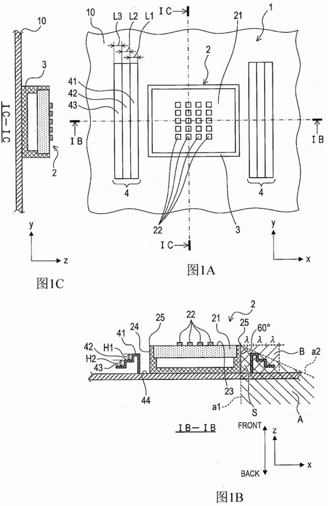
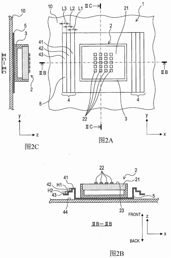
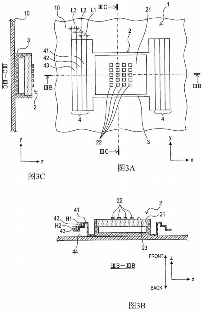
[0038] A radar device 1 shown in FIG. 1 includes an antenna unit 2 and a radio wave reflection unit 4 . The antenna unit 2 includes a case 3 . In addition, the radar device 1 may include a cover for protecting the antenna unit 2 .

[0039] In addition, the radar device 1 includes a transmission and reception circuit for transmitting and receiving radiated waves and reflected waves via the antenna unit 2 , a signal processing unit for processing received signals received by the transmission and reception circuit in order to obtain information on surrounding objects, and the l...

no. 2 approach

[0100] [2-1. Structure]

[0101] Since the basic structure of the second embodiment is the same as that of the first embodiment, the differences will be described below. In addition, the same reference numerals as the first embodiment denote the same structures, and the previous description is referred to.

[0102] As shown in FIG. 14 , in the radar apparatus 101 in the second embodiment, the two radio wave reflection units 400 are directly provided on the vehicle 10 . The radio wave reflection parts 400 are arranged so as to face each other along the x-axis direction in the figure so as to sandwich the antenna part 2 therebetween. The two radio wave reflection parts 400 have symmetrical shapes in the azimuth detection direction. Hereinafter, focusing on one radio wave reflection part 400 , the structure and shape of the radio wave reflection part 400 will be specifically described.

[0103] The radio wave reflection part 400 has a curved surface part 401 . The curved port...


PUM


Abstract

The invention relates to a radar device and the bracket for the radar device. A radar device (1, 101) is for detecting an object present in a predetermined detection range by radiating radio waves, and is provided with an antenna part (2) and a radio wave reflection part (4, 400). The antenna part is configured to radiate radio waves. The radio wave reflection part is disposed in a region that is around the antenna part and that is out of the detection range, and has a reflection surface, the height of which with respect to an installation surface (44) of the radar device gradually changes.

Description

[0001] Cross References to Related Applications [0002] This international application claims priority based on Japanese Patent Application No. 2019-73423 filed with the Japan Patent Office on April 8, 2019, and the entire content of Japanese Patent Application No. 2019-73423 is incorporated by reference in this international application. technical field [0003] The present disclosure relates to a radar device and a radar device bracket used for the radar device. Background technique [0004] Millimeter-wave radars used for automatic driving of vehicles, collision prevention, and the like are known. Millimeter wave radar is a radar that irradiates radio waves and detects the reflected waves of the irradiated radio waves reflected by objects to detect the existence of objects within a predetermined detection area and the distance to the objects. In such a millimeter-wave radar, there are radio waves that deviate from a desired irradiation range or go around undesired areas...

Claims


Application Information

Patent Timeline
IPC IPC(8): H01Q15/18H01Q19/17G01S7/03G01S13/931
CPCG01S13/931H01Q15/18G01S7/03G01S7/027H01Q1/3233H01Q19/18H01Q21/065
Inventor 樱井一正境俊哉
Owner DENSO CORP
Why Eureka
Eureka Blog
Learn More