
A Measuring System of Myopia Diopter

A measurement system, myopia technology, applied in the field of myopia diopter measurement system, can solve the problems of slow measurement image speed, long optometry time, etc., achieve the effect of reducing the time used for optometry and speeding up the imaging speed

Active Publication Date: 2022-02-08
北京茗视光眼科医院管理有限公司
View PDF13 Cites 0 Cited by
  • Summary
  • Abstract
  • Description
  • Claims
  • Application Information

AI Technical Summary

Problems solved by technology

[0004] Therefore, the present invention provides a measurement system of myopia diopter, which is used to overcome the problem in the prior art that the full-automatic computer refractometer acquires clear measurement images at a slow speed, which leads to long refraction time.

Method used


Image

  • A Measuring System of Myopia Diopter
  • A Measuring System of Myopia Diopter

Examples


Embodiment Construction

[0059] In order to make the objects and advantages of the present invention clearer, the present invention will be further described below in conjunction with the examples; it should be understood that the specific examples described here are only for explaining the present invention, and are not intended to limit the present invention.

[0060] Preferred embodiments of the present invention are described below with reference to the accompanying drawings. Those skilled in the art should understand that these embodiments are only used to explain the technical principle of the present invention, and are not intended to limit the protection scope of the present invention.

[0061] It should be noted that, in the description of the present invention, terms such as "upper", "lower", "left", "right", "inner", "outer" and other indicated directions or positional relationships are based on the terms shown in the accompanying drawings. The direction or positional relationship shown is ...


PUM


Abstract

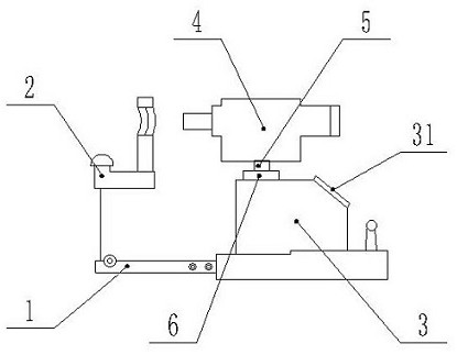
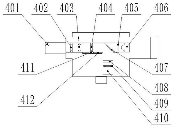
The invention relates to a measurement system for myopia diopter, which includes a body, a headrest, a control integration, and an optometry integration. The control integration is provided with a central control module; the optometry integration is equipped with an infrared light source, a fixed concave lens, a fixed convex lens, and a moving convex lens. Projected image, light source, beam splitter, imaging lens, imaging diaphragm, image sensor. The present invention transmits the imaging image to the central control module through the image sensor, and the central control module is provided with a standard clear image, and the central control module compares the imaging image with the standard clear image to determine the definition value of the imaging image, according to The sharpness value determines the moving speed of the sliding table. When the sharpness value is lower, the moving speed of the sliding table is faster. When the sharpness value gradually increases, the moving speed of the sliding table gradually decreases. Clear fundus images also speed up the imaging speed of clear images, reducing the time spent on optometry.

Description

technical field [0001] The invention relates to the technical field of eye measurement, in particular to a system for measuring the diopter of myopia. Background technique [0002] The computer refractor adopts an objective measurement method, which projects an infrared image onto the fundus of the human eye, generates a scattering image on the retina of the human eye, and calculates the diopter of the eye objectively by analyzing the measurement image collected by the CCD. During the measurement of the traditional computer optometry, the operator gently controls the front, back, left, right, up and down movement of the instrument with his hand, captures the pupil of the subject's eye, aligns it with the pupil of the eyeball, and presses the measurement button to obtain the measurement result. will be displayed on the screen immediately. [0003] Traditional computer refractometers have extremely high requirements for operators. With the development of technology, fully aut...

Claims


Application Information

Patent Timeline
Patent Type & Authority Patents(China)
IPC IPC(8): A61B3/103A61B3/12A61B3/14
CPCA61B3/103A61B3/12A61B3/14
Inventor 于泓周跃华李福生陶冶曲冬懿王燊王小洁赵敏
Owner 北京茗视光眼科医院管理有限公司
Learn More