Tissue clamp assembly and clamp forceps

A technology of tissue clips and components, applied in surgical forceps, medical science, surgery, etc., can solve problems such as collision interference and affecting the normal operation

Pending Publication Date: 2021-11-19
THE FIRST AFFILIATED HOSPITAL OF MEDICAL COLLEGE OF XIAN JIAOTONG UNIV
View PDF0 Cites 0 Cited by
  • Summary
  • Abstract
  • Description
  • Claims
  • Application Information

AI Technical Summary

Problems solved by technology

[0003] The main purpose of the present invention is to provide a tissue clamp assembly and clamps to at least solve the problem that the surgical forceps pulling lung or esophageal tissue collide with other surgical instruments in the existing single-port thoracoscopic surgery and interfere with each other to affect the normal operation.

Method used


Image

  • Tissue clamp assembly and clamp forceps
  • Tissue clamp assembly and clamp forceps
  • Tissue clamp assembly and clamp forceps

Examples


Embodiment 1

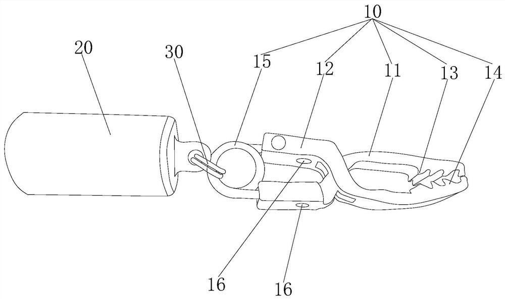
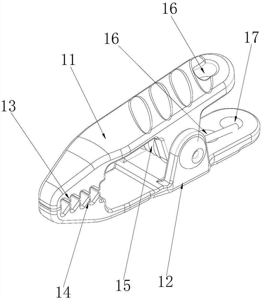
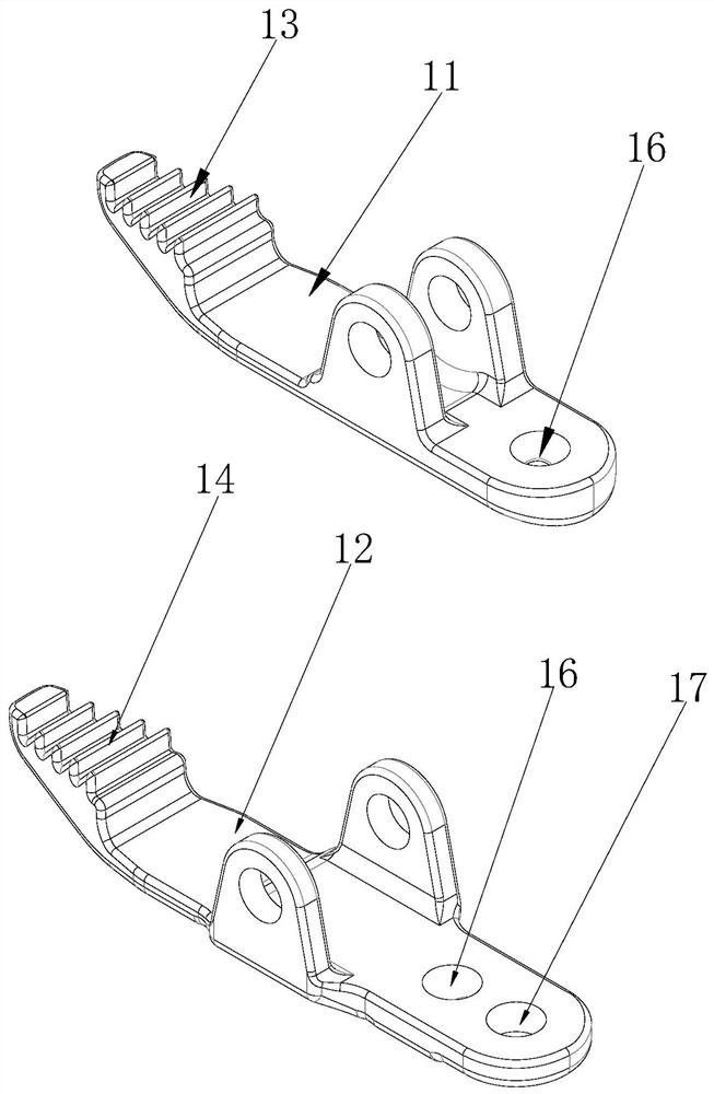
[0037] In this embodiment, the first toothed chuck 13 and the second toothed chuck 14 are multiple; the first toothed chuck 13 and the second toothed chuck 14 are all bar teeth, and the first toothed Chuck 13 extends along the width direction of first clamping arm 11, and a plurality of first toothed chucks 13 are arranged at intervals along the length direction of first clamping arm 11 and are parallel to each other; 12 extends in the width direction, and a plurality of second toothed chucks 14 are arranged at intervals along the length direction of the second clamp arm 12 and are parallel to each other; a plurality of first toothed chucks 13 and a plurality of second toothed chucks 14 are arranged along the The positions in the longitudinal direction of the first clamping arm 11 or the second clamping arm 12 correspond one to one. The tooth tips of the chucks 14 face up and down one by one, and the distance between the tooth tips of each pair of the first toothed chuck 13 an...

Embodiment 2

[0041] In this embodiment, the first toothed chuck 13 and the second toothed chuck 14 are multi-row, and each row of the first toothed chuck 13 and the second toothed chuck 14 are multiple; The first toothed clamps 13 are arranged at intervals along the length direction of the first clamp arm 11, and a plurality of first toothed clamps 13 of each row are arranged at intervals along the width direction of the first clamp arm 11; the second toothed clamps of multiple rows The heads 14 are arranged at intervals along the length direction of the second clamping arm 12 , and a plurality of second toothed chucks 14 in each row are arranged at intervals along the width direction of the second clamping arm 12 .

[0042] The number of the first toothed chuck 13 or the second toothed chuck 14 of each row is not equal, and the width of the first clamping portion and the second clamping portion is along the rear of the first clamping arm 11 or the second clamping arm 12. The direction fro...

Embodiment 3

[0046] In this embodiment, the first toothed chuck 13 and the second toothed chuck 14 are multi-row, and each row of the first toothed chuck 13 and the second toothed chuck 14 are multiple; The first toothed clamps 13 are arranged at intervals along the length direction of the first clamp arm 11, and a plurality of first toothed clamps 13 of each row are arranged at intervals along the width direction of the first clamp arm 11; the second toothed clamps of multiple rows The head 14 is arranged at intervals along the length direction of the second clamping arm 12, and a plurality of second toothed chucks 14 of each row are arranged at intervals along the width direction of the second clamping arm 12; the first toothed chucks 13 of multiple rows and the multiple rows The position of the second toothed chuck 14 along the length direction of the first clamp arm 11 or the second clamp arm 12 corresponds one by one, and each row of multiple first toothed chucks 13 corresponds to a ro...


PUM


Abstract

The invention provides a tissue clamp assembly and clamp forceps, wherein the tissue clamp assembly comprises a tissue clamp and a traction magnet, the tissue clamp comprises a first clamping arm, a second clamping arm and a spring body, and the first clamping arm and the second clamping arm are hinged to each other; a first clamping part and a second clamping part are formed at the front end of the first clamping arm and the front end of the second clamping arm respectively, the first clamping part is provided with a first tooth-shaped chuck, the second clamping part is provided with a second tooth-shaped chuck, and the two ends of the spring body are connected with the first clamping arm and the second clamping arm respectively; corresponding clamping holes are formed in the rear end of the first clamping arm and the rear end of the second clamping arm; the traction magnet is connected with the tissue clamp through a connecting ring; the first tooth-shaped chuck and the second tooth-shaped chuck clamp human tissues under the action of the spring body; and the traction magnet is used for pulling the human tissues through the tissue clamp under the action of the attraction force of the external anchoring magnet. Therefore, when a single-hole thoracoscope operation is carried out, lung or esophageal tissue can be effectively pulled, and other surgical instruments cannot be collided or interfered.

Description

technical field [0001] The invention relates to the field of thoracic surgery equipment, in particular to a tissue clamp assembly and clamps. Background technique [0002] At present, thoracoscopic minimally invasive surgery is the development direction of thoracic surgery, and single-port thoracoscopic surgery has been recognized by the majority of thoracic surgeons. At present, in the operation process, the lung or esophagus tissue is generally pulled by ordinary surgical forceps, and then the corresponding surgical resection or other operations are performed. Since the surgical forceps for pulling the lung or esophagus tissue need to pass through the surgical incision, the lung or esophagus tissue needs to be stretched. Or the surgical forceps of esophageal tissue will collide with other surgical instruments and interfere with each other, affecting the normal operation of the operation. Contents of the invention [0003] The main purpose of the present invention is to ...

Claims


Application Information

Patent Timeline
Patent Type & Authority Applications(China)
IPC IPC(8): A61B17/02A61B17/29
CPCA61B17/0218A61B17/29A61B2017/2926
Inventor 张勇汤博周振宇刘科严小鹏付军科吕毅荆王莉王浩华马锋
Owner THE FIRST AFFILIATED HOSPITAL OF MEDICAL COLLEGE OF XIAN JIAOTONG UNIV
Why Eureka
Try Eureka