Valve-controlled shot circulating device of shot blasting machine

A valve control and circulation device technology, which is applied to the used abrasive processing device, abrasive feeding device, abrasive and other directions, can solve the problems of energy loss, poor permeability of fiber plastics, time difference, etc., to reduce the waste of pellets and the effect of artificial waste

Active Publication Date: 2021-11-19
广东精久重工科技有限公司
View PDF20 Cites 0 Cited by
  • Summary
  • Abstract
  • Description
  • Claims
  • Application Information

AI Technical Summary

Problems solved by technology

[0003] But this valve combination method has the following defects, one of which is that because the silo is on the top of the shot blasting machine, fiber plastic soft material is used between the silo and the shot blasting machine. Pipe connection, fiber plastic has poor permeability, you can’t clearly see the flow rate of the steel shot entering the blasting machine, whether it is clean or not, if the stop valve is damaged, the steel shot will not flow into the shot blasting machine, and

Method used


Image

  • Valve-controlled shot circulating device of shot blasting machine
  • Valve-controlled shot circulating device of shot blasting machine
  • Valve-controlled shot circulating device of shot blasting machine

Examples


Embodiment Construction

[0028] The following will clearly and completely describe the technical solutions in the embodiments of the present invention with reference to the drawings in the embodiments of the present invention.

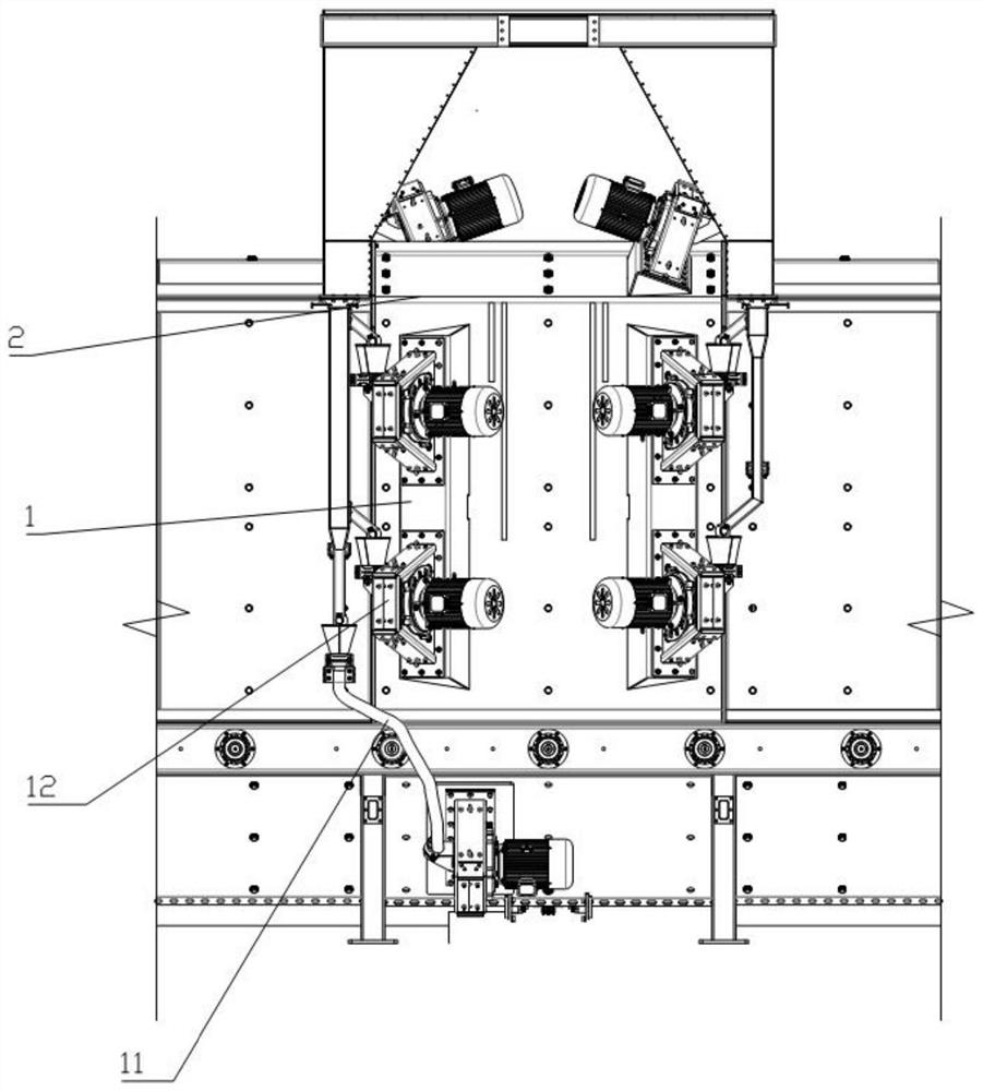
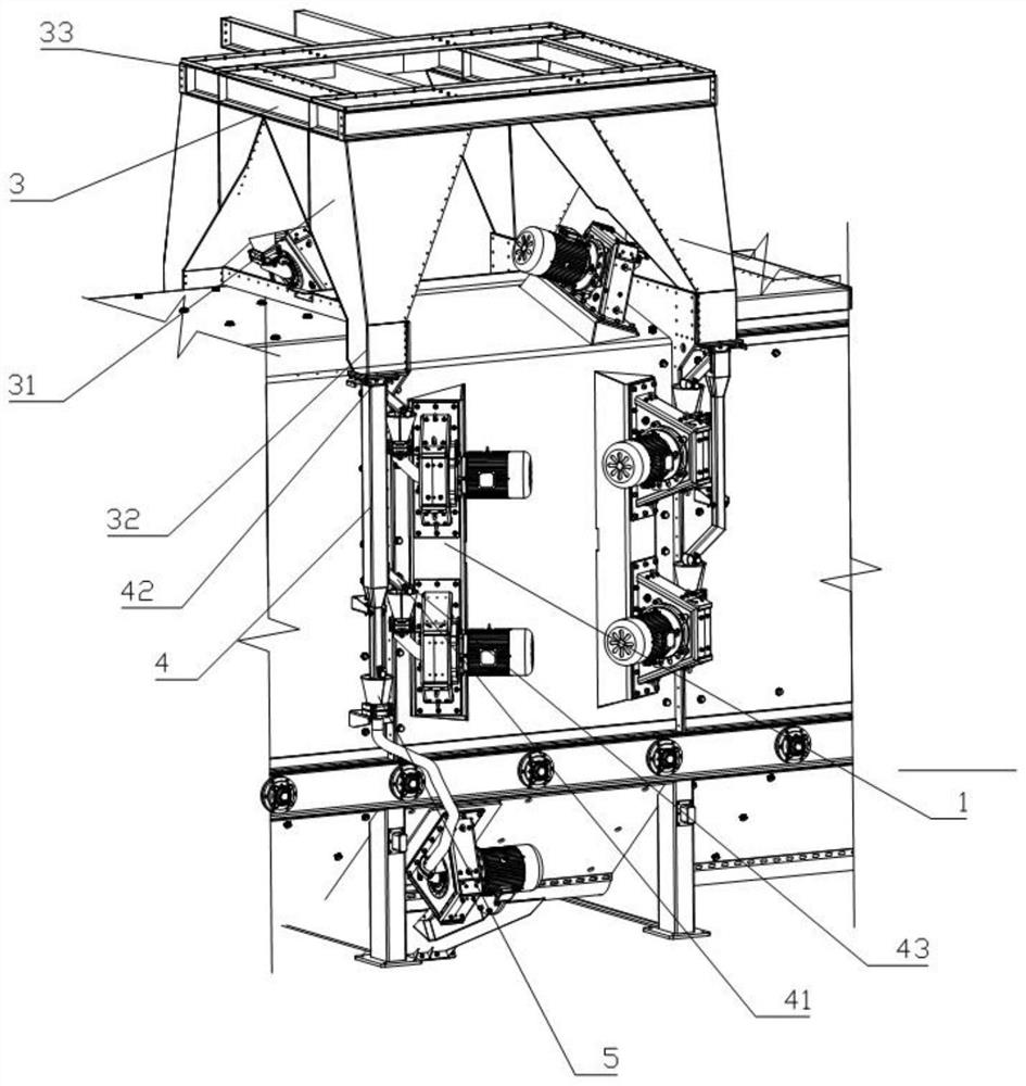
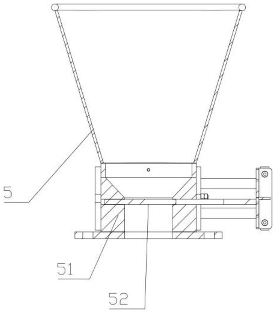
[0029] see Figure 1-5 , in Embodiment 1 of the present invention, the combined application of valves in the shot blasting machine shot material circulation system includes a mounting frame 2 and a shot blasting device 1 located in the mounting frame 2, and also includes a feed bin group 3 and shot blasting equipment. The silo group 3 is placed on the upper end of the installation frame 2 and is fixedly connected with the installation frame 2; the feed bin group 3 is provided with a plurality of silo bodies, and the bottom of each silo body is provided with feeding pipe fittings, and the feeding pipe fittings are placed in the feed bin group 3. The lower end of the silo group 3 surrounds the outside of the installation frame 2, and the feeding pipes communicate with each silo ...


PUM


Abstract

The invention discloses a valve-controlled shot circulating device of a shot blasting machine. The device comprises a mounting frame and shot blasting devices arranged in the mounting frame, and further comprises a feeding bin group and shot blasting equipment, the feeding bin group is arranged at the upper end of the mounting frame and is fixedly connected with the mounting frame, a plurality of bin bodies are arranged on the feeding bin group, the bottom end of each bin body is provided with a feeding pipe fitting, the feeding pipe fittings are arranged at the lower end of the feeding bin group and surround the mounting frame, the shot blasting equipment comprises the shot blasting devices arranged in the mounting frame, all the shot blasting devices are connected with all the feeding pipe fittings, and transition bins are arranged at the joints of the shot blasting devices and the feeding pipe fittings. According to the shot circulating device of the shot blasting machine, the transition bins and control valves are arranged at the joints of the shot blasting devices and the feeding pipe fittings, and the problem that the shot blasting devices are greatly damaged due to the fact that steel shots cannot be cut off in time is solved through the control valves; and energy waste or unnecessary abrasion caused by idle running of the shot blasting devices or unnecessary abrasion due to the fact that the flow of steel shots entering the shot blasting devices cannot be observed and whether the steel shots are separated completely is reduced through the transition bins, and the reliability is higher.

Description

technical field [0001] The invention relates to a shot blasting machine, in particular to a shot blasting machine pellet circulation device controlled by a valve. Background technique [0002] In the existing shot blasting machine equipment, the steel shot enters the silo after being separated by a separator, and then a flow valve and a stop valve are set at the lower part of the silo, or the flow valve and the stop valve are combined into one, and the lower part of the valve is connected to a fiber plastic hose , the other end of the hose is directly connected to the shot blaster to form a closed loop from the silo to the shot blaster to transport the shot. [0003] However, this valve combination method has the following defects. One of them is that because the hopper is on the top of the shot blasting machine, fiber plastic hoses are used to connect the hopper to the shot blaster. The fiber plastic has poor permeability and cannot be clearly seen. The size of the steel s...

Claims


Application Information

Patent Timeline
IPC IPC(8): B24C7/00B24C3/02B24C9/00
CPCB24C7/00B24C3/02B24C9/00
Inventor 孟凡书
Owner 广东精久重工科技有限公司
Why Eureka
Try Eureka