New energy automobile tire packaging equipment
A new energy vehicle and packaging equipment technology, which is applied in the field of new energy vehicle tire packaging equipment, can solve the problems of low work efficiency, boring work, laborious work, etc., and achieve the effect of high work efficiency and avoiding deviation
- Summary
- Abstract
- Description
- Claims
- Application Information
AI Technical Summary
Problems solved by technology
Method used
Image

Examples
Embodiment 1
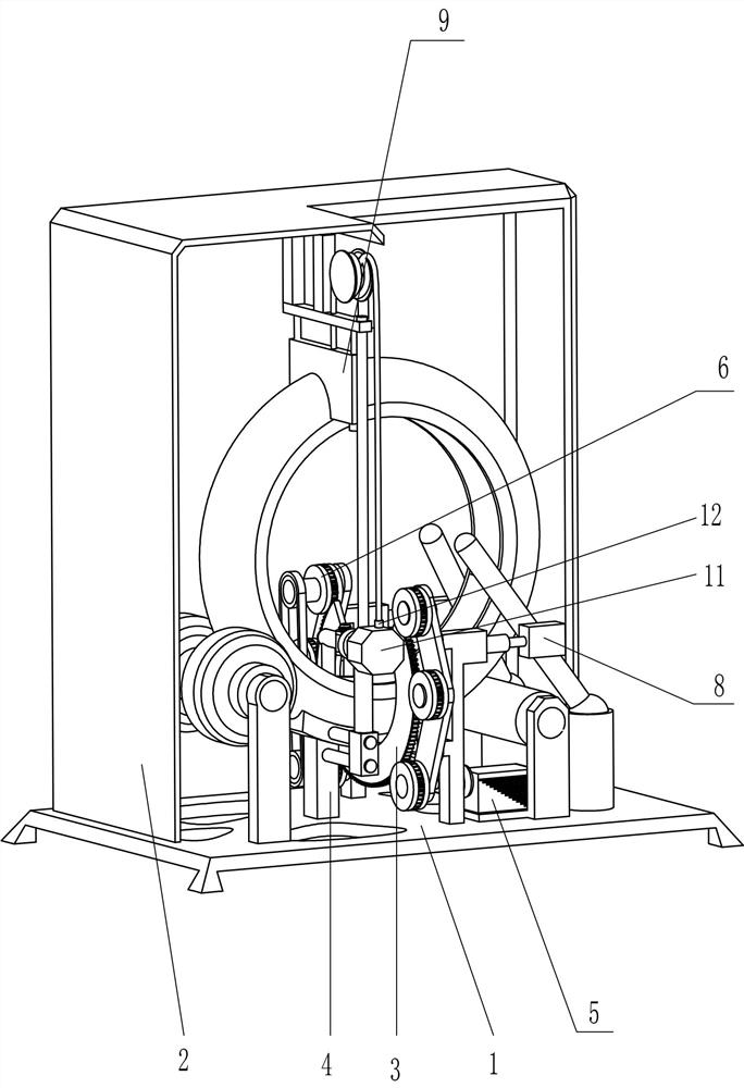
[0027] A new energy vehicle tire packaging equipment, such as figure 1 , figure 2 , image 3 , Figure 4 and Figure 7 As shown, it includes a base 1, a fixed frame 2, an arc-shaped toothed plate 3, a fixed guide block 4, a protruding rod 41, a driving mechanism 5, a rotating mechanism 6 and an auxiliary mechanism 7, and the top of the base 1 is fixedly connected with the fixed frame 2. A fixed guide block 4 is fixedly connected to the left middle side of the top of the base 1, a driving mechanism 5 is provided on the base 1, a rotating mechanism 6 is provided on the driving mechanism 5, an arc-shaped toothed plate 3 is arranged on the rotating mechanism 6, and an arc-shaped toothed plate 3 is arranged on the rotating mechanism 6. A protruding rod 41 is provided on the left front of the board 3 , and an auxiliary mechanism 7 is provided between the base 1 and the fixed frame 2 .
[0028] The drive mechanism 5 includes a first motor 51, a first rotating shaft 52, a first r...
Embodiment 2
[0033] On the basis of Example 1, such as figure 1 , Figure 4 and Figure 5Shown, also include fixing mechanism 8, fixing mechanism 8 includes telescoping rod 81, second fixing block 82, back-moving spring 83, universal seat 84 and limit rod 85, first fixing rod 55 right side upper part is affixed Telescopic rod 81 is arranged, and the right end of telescopic rod 81 is fixedly connected with the second fixed block 82, and base 1 top right side is provided with universal seat 84 symmetrically front and back, and the universal seat 84 is rotated and is provided with limit rod 85, and the outer limit rod 85 A return spring 83 is provided between the middle part of the side and the inner side of the second fixing block 82 .
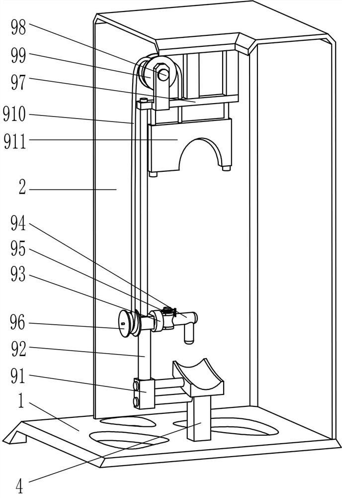
[0034] Also comprise limit mechanism 9, limit mechanism 9 comprises second fixed rod 91, the 3rd fixed rod 92, rotating rod 93, L-shaped swing rod 94, torsion spring 95, the first wire wheel 96, special-shaped fixing frame 97, The third rotating shaft 98,...
Embodiment 3
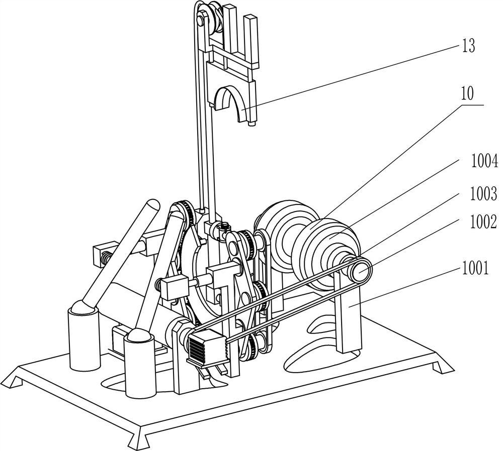
[0038] On the basis of embodiment 1 and embodiment 2, such as figure 2 and Figure 6 As shown, a driven mechanism 10 is also included. The driven mechanism 10 includes a third fixed block 1001, a fourth rotating shaft 1002, a transmission assembly 1003 and a limit roller 1004. The fixed block 1001, the upper part of the third fixed block 1001 on the front and rear sides is rotatably provided with a fourth rotating shaft 1002, and a transmission assembly 1003 is connected between the circumferential direction of the rear part of the fourth rotating shaft 1002 and the circumferential direction of the rear part of the second rotating shaft 73, and the middle part of the fourth rotating shaft 1002 The limit roller 1004 is affixed circumferentially.
[0039] It also includes a special-shaped frame 11, a guide ring 12 and a sponge block 13. The fixed frame 2 is provided with a special-shaped frame 11 on the lower right side of the front side. The first wire wheel 96 is located in ...
PUM
 Abstract
Description
Claims
Application Information
 - R&D Engineer
- R&D Manager
- IP Professional
- Industry Leading Data Capabilities
- Powerful AI technology
- Patent DNA Extraction
Browse by: Latest US Patents, China's latest patents, Technical Efficacy Thesaurus, Application Domain, Technology Topic.
© 2024 PatSnap. All rights reserved.Legal|Privacy policy|Modern Slavery Act Transparency Statement|Sitemap