
Shot and flash synchronization method, device and system

A technology for synchronizing systems and projectiles, applied in ammunition, ammunition testing, weapon accessories, etc., can solve problems such as reducing the probability of successful testing and huge differences in time scales

Pending Publication Date: 2021-11-19
INST OF FLUID PHYSICS CHINA ACAD OF ENG PHYSICS
View PDF6 Cites 0 Cited by
  • Summary
  • Abstract
  • Description
  • Claims
  • Application Information

AI Technical Summary

Problems solved by technology

[0002] Flash X-ray photography is widely used in dynamic tests to shoot test images such as impact, shock wave, and shock deformation. The flash pulse width of this type of X-flash machine is extremely short (ns level), so it is necessary to ensure precise synchronization between the impact moment and the flash moment , otherwise the required image cannot be captured correctly. However, the projectile motion is a tens of millisecond mechanical motion, and the time scale difference between the two is huge, so synchronization is highly challenging. The initial conditions of the cannon (air pressure, projectile mass, etc.) are calculated by calculating the expected bullet speed, and then use the predicted bullet speed to set the timing sequence of the X flasher. This solution is feasible under the condition that a large synchronization error is allowed, but the air gun The state cannot be completely the same between each round of operation, and the air pressure, projectile quality, inner bore flash cleanliness, etc. are all changing. Theoretical calculations cannot take into account so many variables. Therefore, under the experimental conditions of nanosecond flash X flash camera, this scheme Synchronization errors of , significantly reduce the probability of trial success

Method used


Image

  • Shot and flash synchronization method, device and system
  • Shot and flash synchronization method, device and system
  • Shot and flash synchronization method, device and system

Examples


Embodiment

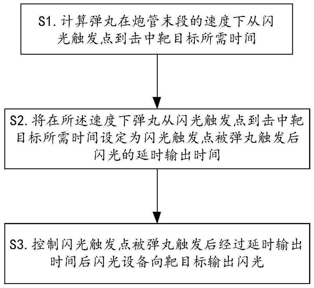
[0058]In order to solve the technical problem in the prior art that the synchronization error between the projectile and the flash is uncertain due to the different states of each projectile, which reduces the probability of test success; in the first aspect, the embodiment of the present invention provides a projectile and flash synchronization methods, including:

[0059] When the projectile hits the target after triggering the flash trigger point, the flash generating device outputs flash to the target.

[0060] refer to Figure 4 Shown, the projectile 1 in the gun barrel 6 is flying in the gun barrel. When the projectile 1 hits the target 4 after triggering the flash trigger point 5, the flash generating device outputs flash to the target.

[0061] Further, when the projectile hits the target after triggering the flash trigger point, the flash generating device outputs flash to the target; including:

[0062] Set the delay output time t of the flash generation device af...


PUM


Abstract

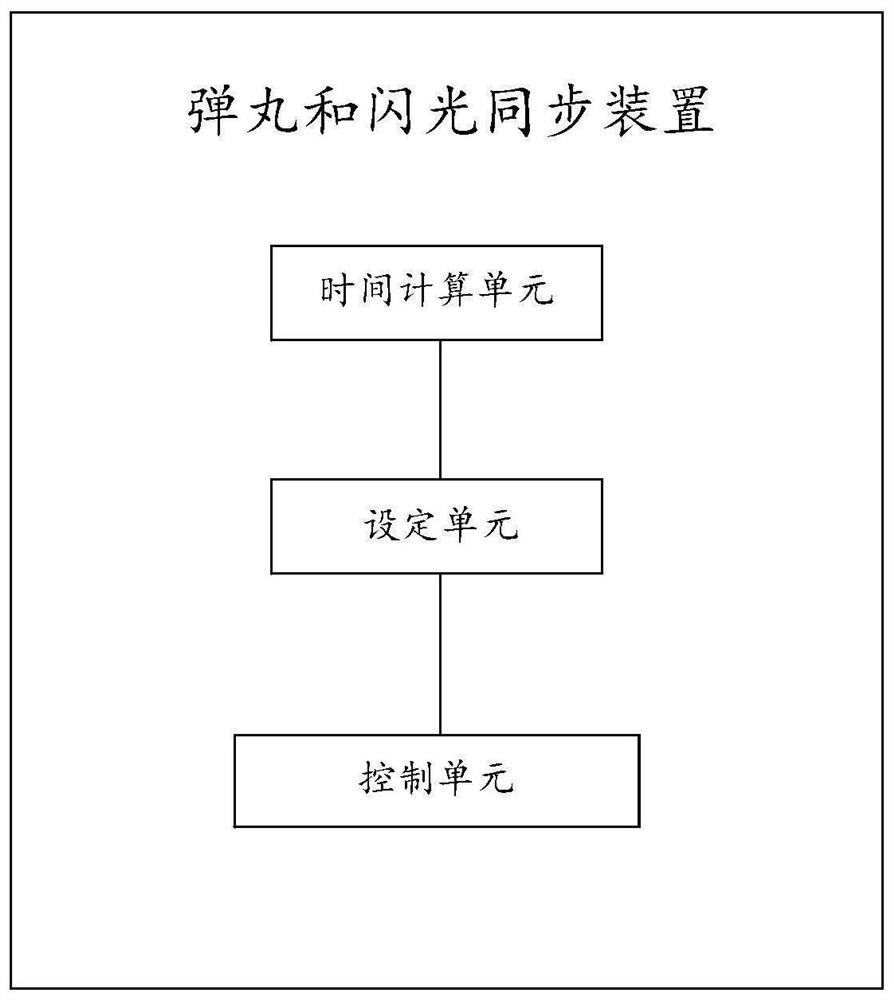
The embodiment of the invention provides a shot and flash synchronization method, device and system to solve the technical problem that in the prior art, due to the fact that the states of all shots are different, synchronization errors between the shots and flash are uncertain, and the test success probability is reduced. The method comprises the steps that when a shot hits a target after triggering a flash triggering point, flash generation equipment outputs flash to the target. The device comprises a time calculation unit; a setting unit used for setting the time required by the shot to hit the target from the flash triggering point at the speed as the delay output time of the flash after the flash triggering point is triggered by the shot; and a control unit used for controlling the flash generation equipment to output the flash to the target after the delayed output time after the flash triggering point is triggered by the shot. According to the embodiment of the invention, when the shot hits the target after triggering the flash triggering point, the flash generation equipment outputs the flash to the target, so that high-precision synchronization of the flash and the shot of a gas gun is realized.

Description

technical field [0001] The invention relates to a projectile and flash synchronization method, device and system. Background technique [0002] Flash X-ray photography is widely used in dynamic tests to shoot test images such as impact, shock wave, and shock deformation. The flash pulse width of this type of X-flash machine is extremely short (ns level), so it is necessary to ensure precise synchronization between the impact moment and the flash moment , otherwise the required image cannot be captured correctly. However, the projectile motion is a mechanical motion of tens of milliseconds, and the time scale difference between the two is huge, so synchronization is highly challenging. The initial conditions of the cannon (air pressure, projectile mass, etc.) are calculated by calculating the expected bullet speed, and then use the predicted bullet speed to set the timing sequence of the X flasher. This solution is feasible under the condition that a large synchronization err...

Claims


Application Information

Patent Timeline
Patent Type & Authority Applications(China)
IPC IPC(8): F41A31/00F42B35/02
CPCF41A31/00F42B35/02
Inventor 杨宇李晶耿力东伍友成付佳斌何泱
Owner INST OF FLUID PHYSICS CHINA ACAD OF ENG PHYSICS
Learn More