
CNC device

A technology of numerical control device and control unit, which is applied in the direction of program control, computer control, general control system, etc., can solve the problems of deterioration of machining accuracy, etc., and achieve the effect of mechanical vibration suppression

Active Publication Date: 2022-07-29
MITSUBISHI ELECTRIC CORP
View PDF6 Cites 0 Cited by
  • Summary
  • Abstract
  • Description
  • Claims
  • Application Information

AI Technical Summary

Problems solved by technology

In this case, in addition to the error in the position of the tool when the tool is moved linearly, an error in the position of the workpiece that occurs when the table is rotated occurs, and the machining accuracy deteriorates.

Method used


Image

  • CNC device
  • CNC device
  • CNC device

Examples


Embodiment approach

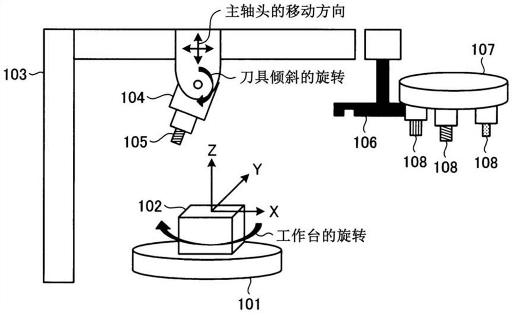
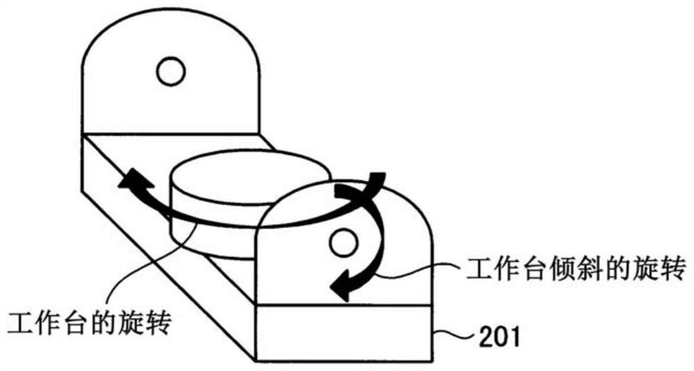
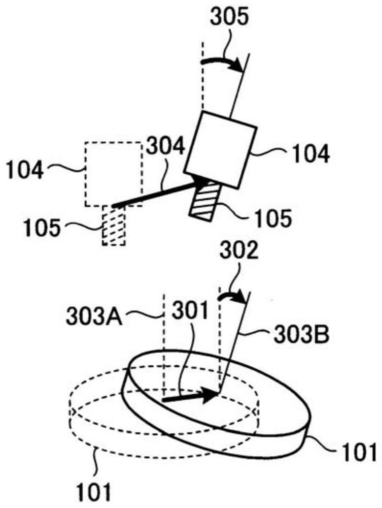
[0024] First, regarding the machine tool to be controlled by the numerical control device according to the present invention, use Figure 1 to Figure 3 Be explained. figure 1 This is a diagram showing a configuration example of a machine tool controlled by a numerical control device.

[0025] figure 1 The work machine shown has a table 101 . The workpiece 102 , which is an object to be processed, is fixed on the table 101 . The table 101 has a rotation axis parallel to the Z axis. In addition, the machine tool has a column 103 . A spindle head 104 is attached to the column 103 , and a tool 105 is attached to the spindle head 104 . In addition, the spindle head 104 has a mechanism for tilting the tool 105 . The numerical control device (not shown) controls the relative position and angle of the tool 105 fixed to the spindle head 104 with respect to the three-dimensional space of the workpiece 102 to make the tool 105 come into contact with the workpiece 102 . In this sta...


PUM


Abstract

A numerical control device (1) for controlling a machine tool (2) having a tool based on a machining program, the numerical control device (1) having: a correction unit (12) for, based on an analysis result of the machining program (5), The correction amount of the position command of the tool related to the rotation axis error included in the mechanical system of the machine tool (2) is calculated; and a movement amount determination unit (16) that moves the rotation axis to the reference position when the correction operation control unit (15) determines to invalidate the correction of the position command.

Description

technical field [0001] The present invention relates to a numerical control device for controlling a processing machine such as a machine tool. Background technique [0002] Industrial processing machines including machine tools are required to perform high-precision and complex processing. The machine tool is usually controlled by a numerical control device, and the drive control is performed so that the tool and the table follow the command path specified by the machining program. The mechanical system of the machine tool to be controlled has a plurality of axes, and is controlled by the numerical control device so that the positions of the respective axes follow the commanded positions. [0003] In order to realize high-precision machining, the numerical control device has the function of changing the moving position of each axis in consideration of the installation error of the mechanical system of the machine tool, the deformation of the mechanical system due to temper...

Claims


Application Information

Patent Timeline
Patent Type & Authority Patents(China)
IPC IPC(8): G05B19/404
CPCG05B19/404
Inventor 末田崇
Owner MITSUBISHI ELECTRIC CORP
Learn More