Moving armature receiver assemblies with vibration suppression
a technology of moving armature and receiver, which is applied in the direction of instruments, frequency/directions obtaining arrangements, sound producing devices, etc., can solve the problems of relatively small compliance or large stiffness of suspensions, low efficiency of mirror-symmetrical dual-receiver design, and oscillation of feedback, etc., to achieve the effect of suppressing vibration of the receiver housing
- Summary
- Abstract
- Description
- Claims
- Application Information
AI Technical Summary
Benefits of technology
Problems solved by technology
Method used
Image
Examples
first embodiment
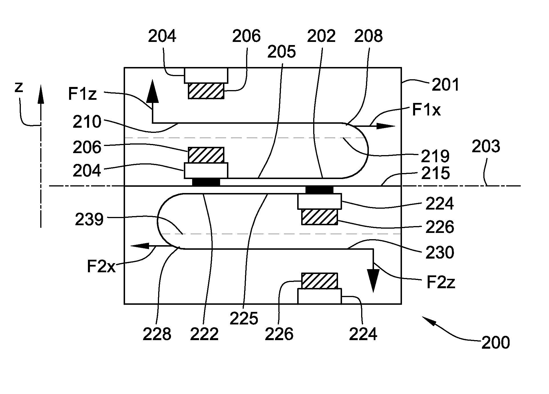
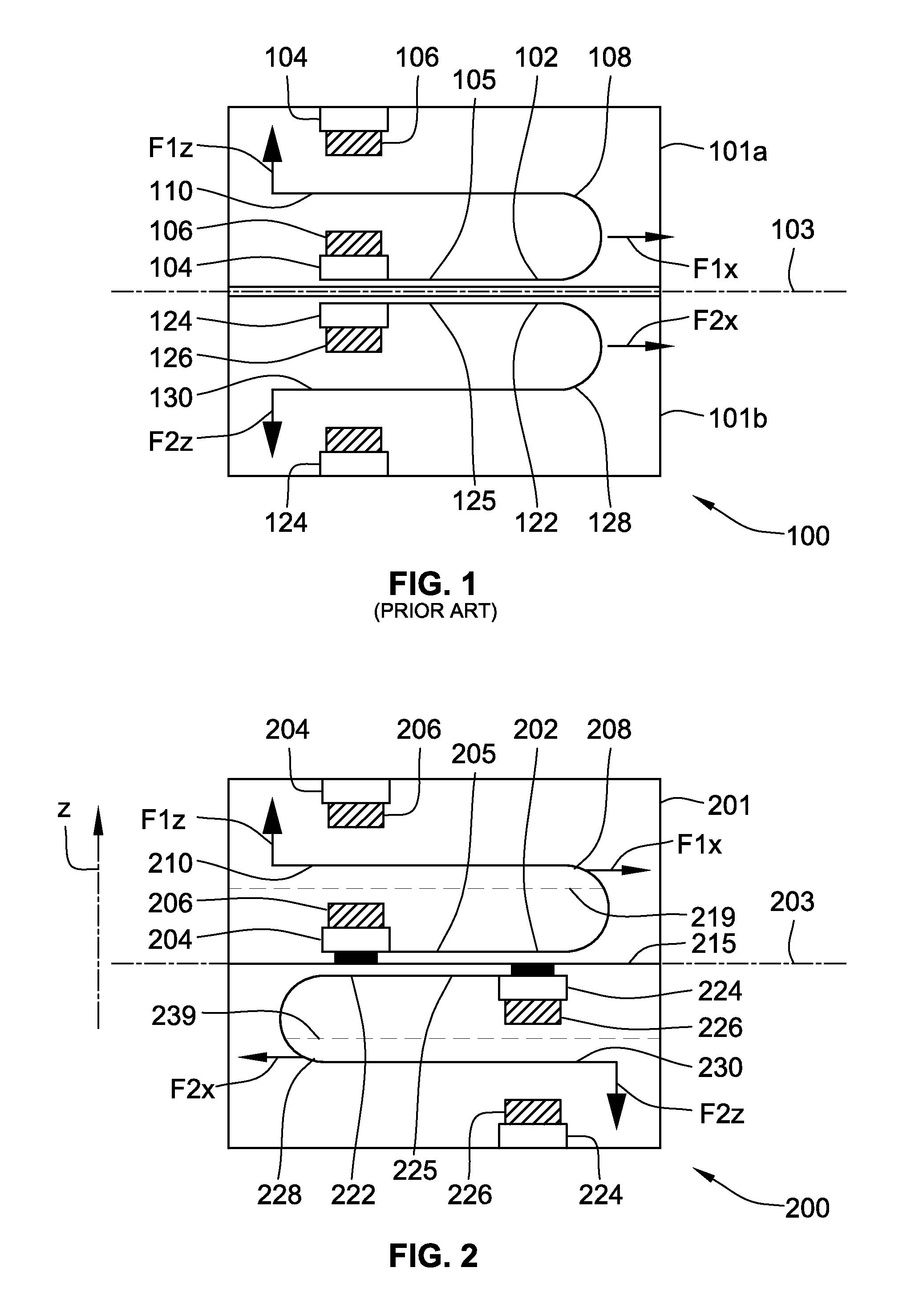
[0050]FIG. 2 is a simplified schematic cross-sectional view of a moving armature receiver assembly 200 or dual-receiver 200 based on two U-shaped armatures 202, 222 in accordance with the invention. The dual-receiver 200 comprises two U-shaped armatures 202, 222 enclosed within a shared housing structure 201 separated by a rigid dividing wall 215. These U-shaped armatures 202, 222 may be conventionally fabricated by machining and bending of a single flat piece of ferromagnetic material. In the alternative, the housing structure may be formed by a pair of rigidly fastened separate housings as discussed above in connection with FIG. 1. The cross-sectional view is taken centrally and vertically, i.e. along a z-axis plane of the housing structure 201. While the upper and lower portions of the dual-receiver 100 are substantially identical in terms of dimensions and materials, the lower portion is rotated 180 degree about the z-axis plane compared to the mirror-symmetrical arrangement dep...
second embodiment
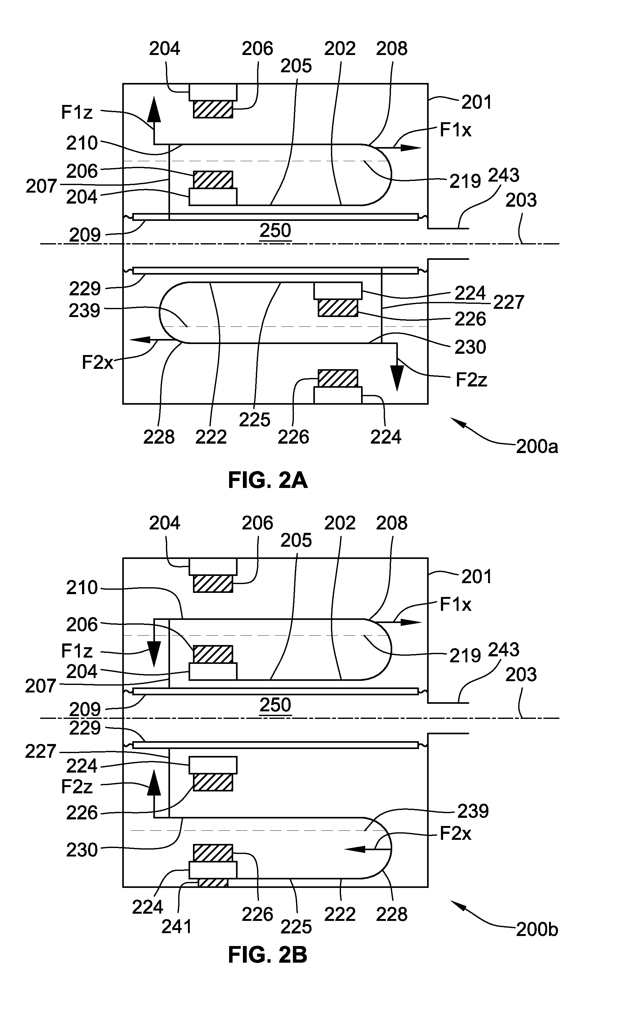
[0057]FIG. 2B is a simplified schematic cross-sectional view of a moving armature receiver assembly 200b or dual-receiver based on two U-shaped armatures 202, 222 in accordance with a 7th embodiment of the invention. Corresponding features of the second embodiment and the present embodiment have been provided with the same reference numerals to ease comparison. The dual-receiver 200b comprises two U-shaped armatures 202, 222 enclosed within a shared housing structure 201. The upper and lower half portion of the dual-receiver 200b is arranged such that the lower U-shaped armature and its associated motor systems, comprising a pair of permanent magnets 226 magnetically coupled to a magnet housing 224, has been turned upside down, i.e. rotated 180 degrees about the lower longitudinal armature plane 239 compared to the embodiment depicted on FIG. 2A. In this manner, the deflectable leg 230 of the lower U-shaped armature 222 faces a lower compliant diaphragm 229. The deflectable leg 210 ...
third embodiment
[0069]FIG. 5 is a simplified schematic cross-sectional view of a dual-receiver based on two U-shaped armatures 502, 522 sharing a common magnet gap 512 in accordance with the invention. The depicted cross-sectional view is taken centrally and vertically, i.e. along a z-axis plane extending as indicated by dotted arrow “z”, of a shared receiver housing (not shown) through the U-shaped armatures 502, 522. The dual-receiver 500 comprises an upper U-shaped armature 502 and a lower U-shaped armature 522 enclosed within the shared receiver housing (not shown). The upper and lower U-shaped armatures 502, 522 may be conventionally fabricated by machining and bending of a single flat piece of ferromagnetic material. The common magnet gap 512 is formed between a pair of permanent magnets 506, 526 which creates a magnetic field within the common magnet gap 512. The upper U-shaped armature 502 comprises a fixed leg 505 attached, and magnetically coupled, to a magnet housing 504 which in turn ma...
PUM
 Abstract
Description
Claims
Application Information
 - R&D
- Intellectual Property
- Life Sciences
- Materials
- Tech Scout
- Unparalleled Data Quality
- Higher Quality Content
- 60% Fewer Hallucinations
Browse by: Latest US Patents, China's latest patents, Technical Efficacy Thesaurus, Application Domain, Technology Topic, Popular Technical Reports.
© 2025 PatSnap. All rights reserved.Legal|Privacy policy|Modern Slavery Act Transparency Statement|Sitemap|About US| Contact US: help@patsnap.com


