Eureka AIR delivers breakthrough ideas for toughest innovation challenges, trusted by R&D personnel around the world.

Crawler bed structure with flushing and cleaning functions

A crawler and functional technology, applied in the field of material conveying equipment, can solve the problems of consuming a lot of manpower, affecting the production efficiency of factory equipment, and poor cleaning effect, and achieve the effect of improving cleanliness

Pending Publication Date: 2021-11-23
合肥金果缘视觉科技有限公司
View PDF6 Cites 2 Cited by
  • Summary
  • Abstract
  • Description
  • Claims
  • Application Information

AI Technical Summary

Problems solved by technology

[0003] In the actual working process, when the moisture content of the material is high and has a certain degree of adhesion, a small part of the material fails to leave the conveying equipment under the action of gravity to complete the discharge after passing through the discharge port, but continues to stick It is attached to the conveying equipment and continues to move, which brings inconvenience to subsequent production and processing
[0004] The crawler bed is wet, easy to stick, and easy to dirty due to the material characteristics, and has extremely high requirements on hygiene. It must be cleaned and cleaned frequently. The existing cleaning and cleaning operations mainly rely on manual work, which requires a lot of labor and manpower, and the cleaning speed Slow, poor cleaning effect, affecting the production efficiency of factory equipment

Method used


Image

  • Crawler bed structure with flushing and cleaning functions
  • Crawler bed structure with flushing and cleaning functions
  • Crawler bed structure with flushing and cleaning functions

Examples


Embodiment Construction

[0024] In order to further explain the technical means and effects of the present invention to achieve the intended purpose of the invention, the specific implementation, structure, features and effects of the present invention will be described in detail below in conjunction with the accompanying drawings and preferred embodiments.

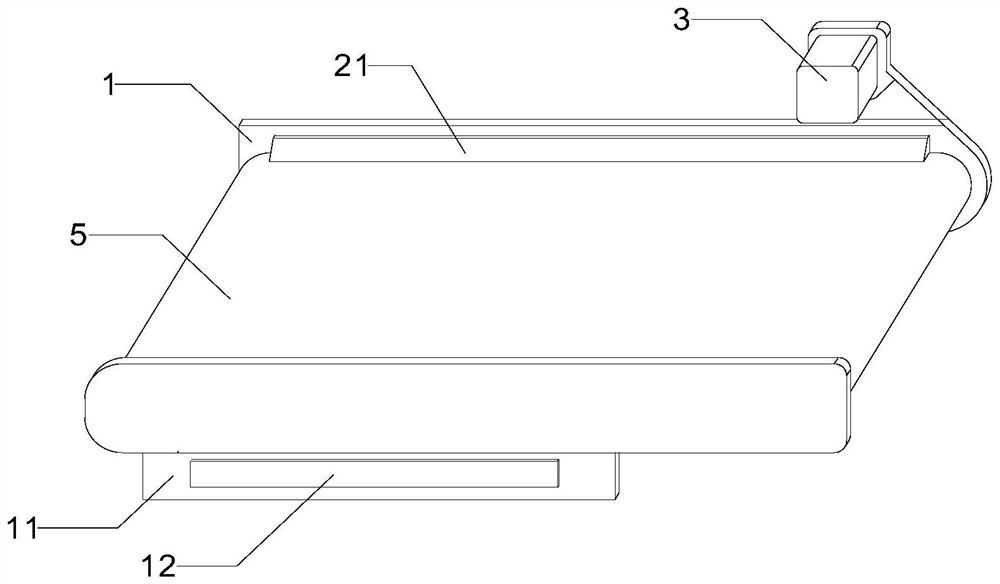
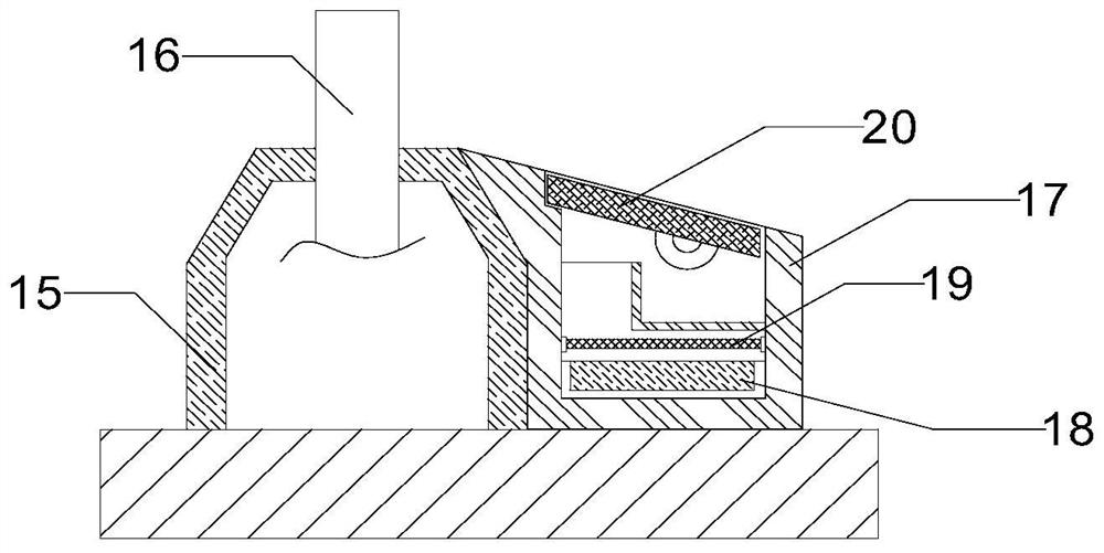
[0025] see Figure 1-5 , in an embodiment of the present invention, a crawler bed structure with flushing and cleaning functions includes a conveyor frame 1, one end of the conveyor frame 1 is rotatably connected with a driving roller 2, and a drive motor 3 is fixedly installed on the top of the conveyor frame 1, and the drive motor The output end of 3 is connected to the driving roller 2 through a belt, and the inner wall of the conveyor frame 1 is connected with several driven rollers 4, and the outer wall of the driving roller 2 is driven by the material conveyor belt 5 and several driven rollers 4. connected, the surface of the material conve...


PUM


Abstract

The invention discloses a crawler bed structure with flushing and cleaning functions. The crawler bed structure comprises a conveying frame, one end of the conveying frame is rotationally connected with a driving rotating roller, a driving motor is fixedly installed at the top of the conveying frame, and the output end of the driving motor is in transmission connection with the driving rotating roller through a belt; and the inner wall of the conveying frame is rotationally connected with a plurality of driven rotating rollers, and the outer wall of the driving rotating roller is in transmission connection with the plurality of driven rotating rollers through a material conveying belt. Through an inclined material taking scraping plate, impurities adhering to the material conveying belt remain on the material taking scraping plate, and a material receiving plate is arranged to receive residues on the material taking scraping plate, so that the cleanliness of the belt surface of the material conveying belt is improved; the upper belt surface of the material conveying belt is fully and uniformly cleaned through water flow sprayed out of a cleaning water pipe; and hot air is generated through a drying fan and an electric heating net to dry the material conveying belt, and the situation that too much water remains on the material conveying belt to affect material conveying is avoided.

Description

technical field [0001] The invention relates to the technical field of material conveying equipment, in particular to a crawler bed structure with flushing and cleaning functions. Background technique [0002] The crawler bed structure is widely used in various material conveying equipment, and is widely used in mines, ports, electric power, chemical industry, building materials, food, mechanical processing and other occasions. [0003] In the actual working process, when the moisture content of the material is high and has a certain degree of adhesion, a small part of the material fails to leave the conveying equipment under the action of gravity to complete the discharge after passing through the discharge port, but continues to stick. It is attached to the conveying equipment and continues to move, which brings inconvenience to subsequent production and processing. [0004] The crawler bed is wet, sticky, and dirty in view of the material characteristics, and has extreme...

Claims


Application Information

Patent Timeline
Patent Type & Authority Applications(China)
IPC IPC(8): B65G45/12B65G45/22B65G45/24B65G45/26B65G21/20F26B21/00
CPCB65G45/12B65G45/22B65G45/24B65G45/26B65G21/2063F26B21/004
Inventor 周虎林李辉方彧方杰江传圣
Owner 合肥金果缘视觉科技有限公司
Why Eureka
Eureka Blog
Learn More