Steel bar blanking equipment and steel bar blanking process of mesh cage networking system

A steel bar and netting technology, applied in the direction of transportation and packaging, conveyor objects, conveyors, etc., can solve the problems of unsatisfactory use of the steel bar blanking system, so as to improve the efficiency of steel bar blanking, improve welding efficiency, and improve the efficiency of steel bar blanking. The effect of material efficiency and accuracy

Active Publication Date: 2021-11-23
ANHUI KEDA IND CO LTD
View PDF9 Cites 0 Cited by
  • Summary
  • Abstract
  • Description
  • Claims
  • Application Information

AI Technical Summary

Problems solved by technology

[0007] Aiming at the unsatisfactory use effect of the existing steel bar blanking system, the present invention provides a steel bar blanking device for a mesh cage network system, which can automatically drop the steel bar to a designated position by its own gravity, and the blanking is accurate and The material speed is fast. In addition, a single blanking channel only drops one steel bar at a time, which avoids the problem that a single blanking channel drops multiple steel bars at one time and causes the steel bars to scatter around.

Method used


Image

  • Steel bar blanking equipment and steel bar blanking process of mesh cage networking system
  • Steel bar blanking equipment and steel bar blanking process of mesh cage networking system
  • Steel bar blanking equipment and steel bar blanking process of mesh cage networking system

Examples


Embodiment

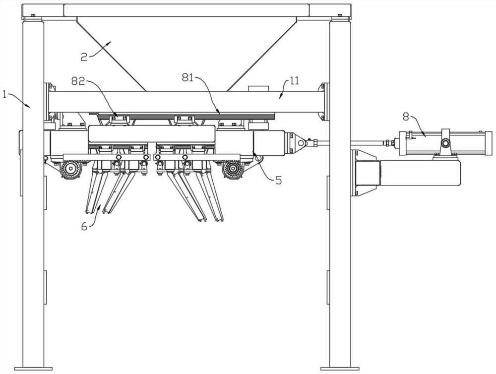
[0043] A kind of steel bar blanking equipment of mesh cage network system, which is used in the production line of steel mesh and mesh cage to realize automatic cutting of steel bars and improve the production efficiency of mesh and mesh cage. The specific structure and structure of the equipment are as follows The working principle is described in detail.

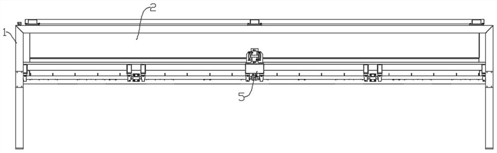
[0044] Such as figure 1 and figure 2 As shown, the steel bar blanking equipment mainly includes a frame 1 , a silo 2 fixedly installed on the upper side of the frame 1 , and a material receiving device and a push-pull device 8 arranged on the lower side of the frame 1 . Wherein, the silo 2 is a funnel structure with upper and lower openings, the upper end is a material inlet, and the lower end is a material outlet, which is convenient for putting steel bars into it.

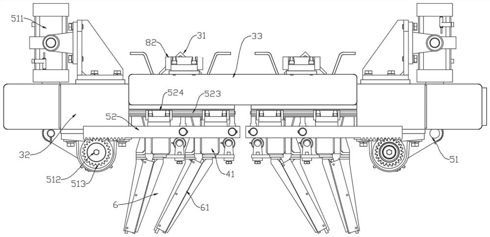
[0045] Such as Figure 2 to Figure 4 As shown, the receiving device includes a receiving channel 3, a blanking channel 4, a pushing mechanism 5, a discha...


PUM


Abstract

The invention discloses steel bar blanking equipment and a steel bar blanking process of a mesh cage networking system, and belongs to the field of steel bar welding. The equipment comprises a rack, a stock bin and a material receiving device, wherein a discharging port of the stock bin is located at the lower end of the stock bin; the material receiving device comprises a material receiving channel, a blanking channel, a material pushing mechanism, a discharging channel and a horizontal channel; an inlet of the material receiving channel is located under the discharging port of the stock bin; an inlet of the blanking channel is positioned below an outlet of the receiving channel; two ends of the horizontal channel are respectively connected with the inlet of the blanking channel and the outlet of the material receiving channel; an inlet of the discharging channel is located under an outlet of the blanking channel; the material pushing mechanism comprises a jacking and pushing unit and a material pushing unit; a pushing plate is arranged on the material pushing unit; a convex block is arranged at the upper end of the pushing plate; the convex block is located in the horizontal channel; and the jacking and pushing unit is used for driving the material pushing unit to move in the horizontal direction. The process adopts the equipment. According to the steel bar blanking equipment and the steel bar blanking process of the mesh cage networking system provided by the invention, steel bar blanking is accurate and rapid, only one steel bar falls off each time through a single blanking channel, and the working stability is high.

Description

technical field [0001] The invention belongs to the technical field of steel bar welding, and more specifically relates to a steel bar blanking device and a blanking process for a mesh cage networking system. Background technique [0002] In the traditional autoclaved aerated concrete slab production industry, the steel mesh cage welding production line is a device that welds the steel bars in the vertical and horizontal directions into a grid-like mesh, and then welds the mesh into a mesh cage. Semi-automatic production, there is no special process for the blanking and conveying of steel bars, and it generally needs manual assistance to complete, which takes up a lot of human resources and low production efficiency, which seriously affects the production capacity of the steel mesh cage welding production line. For this, some steel bar blanking devices have also occurred on the market. [0003] The Chinese patent application number is: CN201910820095.4, and the publication ...

Claims


Application Information

Patent Timeline
Patent Type & Authority Applications(China)
IPC IPC(8): B65G47/82
CPCB65G47/82B65G2201/0217
Inventor 王文昌齐国良徐顺武程阔杨梅
Owner ANHUI KEDA IND CO LTD
Why Eureka
Try Eureka