Testing device and method based on vehicle-mounted multi-connected screen
A testing device and multi-screen technology, which is used in measurement devices, optical testing of flaws/defects, and material analysis by optical means. screen brightness and other issues
- Summary
- Abstract
- Description
- Claims
- Application Information
AI Technical Summary
Problems solved by technology
Method used
Image
Examples
Embodiment 1
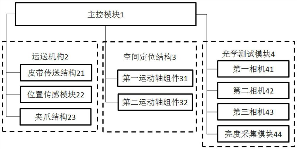
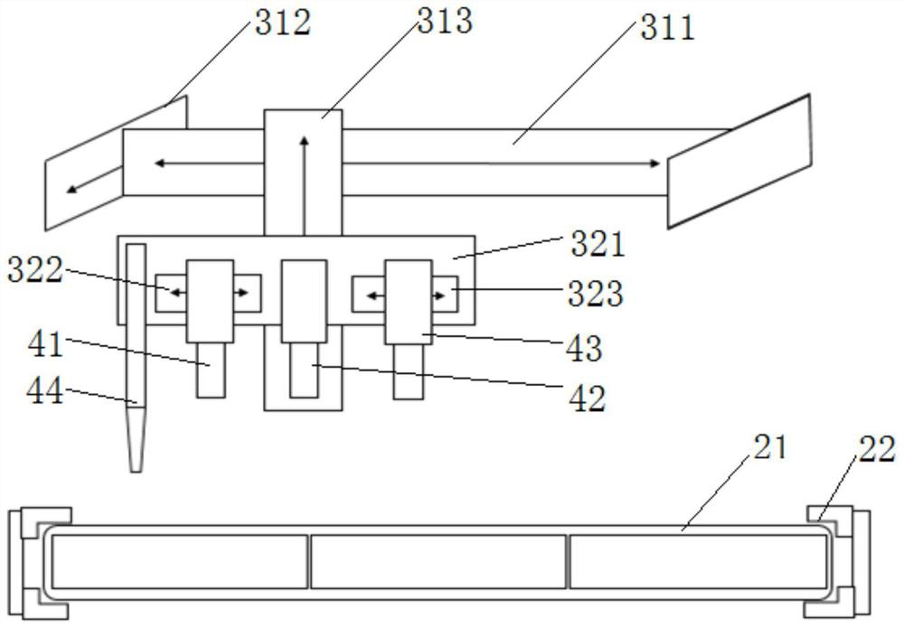
[0052] The reference numerals in the accompanying drawings of the description in this embodiment include: the main control module 1; the transport mechanism 2, the belt transmission structure 21, the position sensing module 22, the jaw structure 23; the space positioning structure 3, the first motion shaft assembly 31 , X-axis fixed frame 311, Y-axis fixed frame 312, Z-axis fixed frame 312; second motion axis assembly 32, fixed bracket 321, first displacement axis 322, second displacement axis 323; optical test module 4, first camera 41 . A second camera 42 , a third camera 43 , and a brightness acquisition module 44 .
[0053] A test device and method based on a vehicle-mounted multi-screen provided by an embodiment of the present invention, such as figure 1 , figure 2 As shown, in this embodiment, it includes the main control module 1 and the transport mechanism 2 connected thereto, the space positioning structure 3, and the optical test module 4. The space positioning str...
Embodiment 2
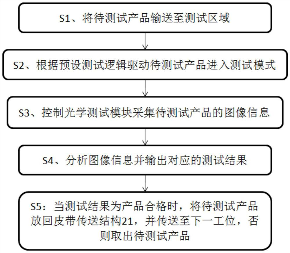
[0092] The embodiment of the present invention also provides a test method based on a vehicle-mounted multi-screen, which is applied to a test device based on a vehicle-mounted multi-screen provided in the above-mentioned embodiment 1, see image 3 , including steps S1-S5:
[0093] S1. Transport the product to be tested to the test area, including steps S11-S12:
[0094] S11. Control the belt conveying structure 21 to transport the product to be tested to the testing station;
[0095] S12. After receiving the determination information from the position sensing module 22, control the jaw structure 23 to lift and / or turn over the product to be tested on the testing station, and move the product to be tested to the testing area.
[0096] S2. Drive the product to be tested to enter the test mode according to the preset test logic;
[0097] S3. Control the optical test module 4 to collect the image information of the product to be tested, including steps S31-S33:
[0098] S31. O...
PUM
 Abstract
Description
Claims
Application Information
 - R&D
- Intellectual Property
- Life Sciences
- Materials
- Tech Scout
- Unparalleled Data Quality
- Higher Quality Content
- 60% Fewer Hallucinations
Browse by: Latest US Patents, China's latest patents, Technical Efficacy Thesaurus, Application Domain, Technology Topic, Popular Technical Reports.
© 2025 PatSnap. All rights reserved.Legal|Privacy policy|Modern Slavery Act Transparency Statement|Sitemap|About US| Contact US: help@patsnap.com


