Power supply system and power supply method

A technology of power supply system and conductive sheet, which is applied in the direction of battery disconnection circuit, load supply circuit, battery circuit device, etc., and can solve problems such as photovoltaic power supply system not having overheat protection capability, service life impact of power supply equipment, and comprehensive utilization of unfavorable energy. , to achieve the effects of alleviating high-power output work, protecting overheating safety, and reducing the incidence of fire

Inactive Publication Date: 2021-11-23
罗嘉璐
View PDF0 Cites 0 Cited by
  • Summary
  • Abstract
  • Description
  • Claims
  • Application Information

AI Technical Summary

Problems solved by technology

[0006] Aiming at the deficiencies of the prior art, the present invention provides a power supply system and a power supply method, which solves the problem that the traditional photovoltaic power supply system does not have the ability to protect the overheating, which affects the service life of the power supply equipment, and even causes high-temperature fires. The traditional overheating Power outages cause waste of power, which is not conducive to the comprehensive utilization of energy

Method used


Image

  • Power supply system and power supply method
  • Power supply system and power supply method
  • Power supply system and power supply method

Examples


Embodiment Construction

[0034] The following will clearly and completely describe the technical solutions in the embodiments of the present invention with reference to the accompanying drawings in the embodiments of the present invention. Obviously, the described embodiments are only some, not all, embodiments of the present invention. Based on the embodiments of the present invention, all other embodiments obtained by persons of ordinary skill in the art without making creative efforts belong to the protection scope of the present invention.

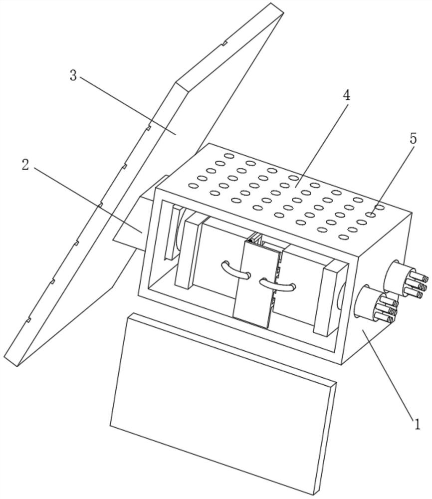
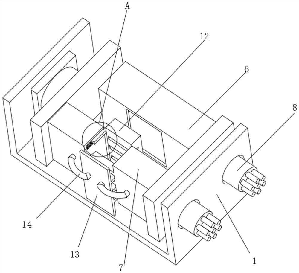
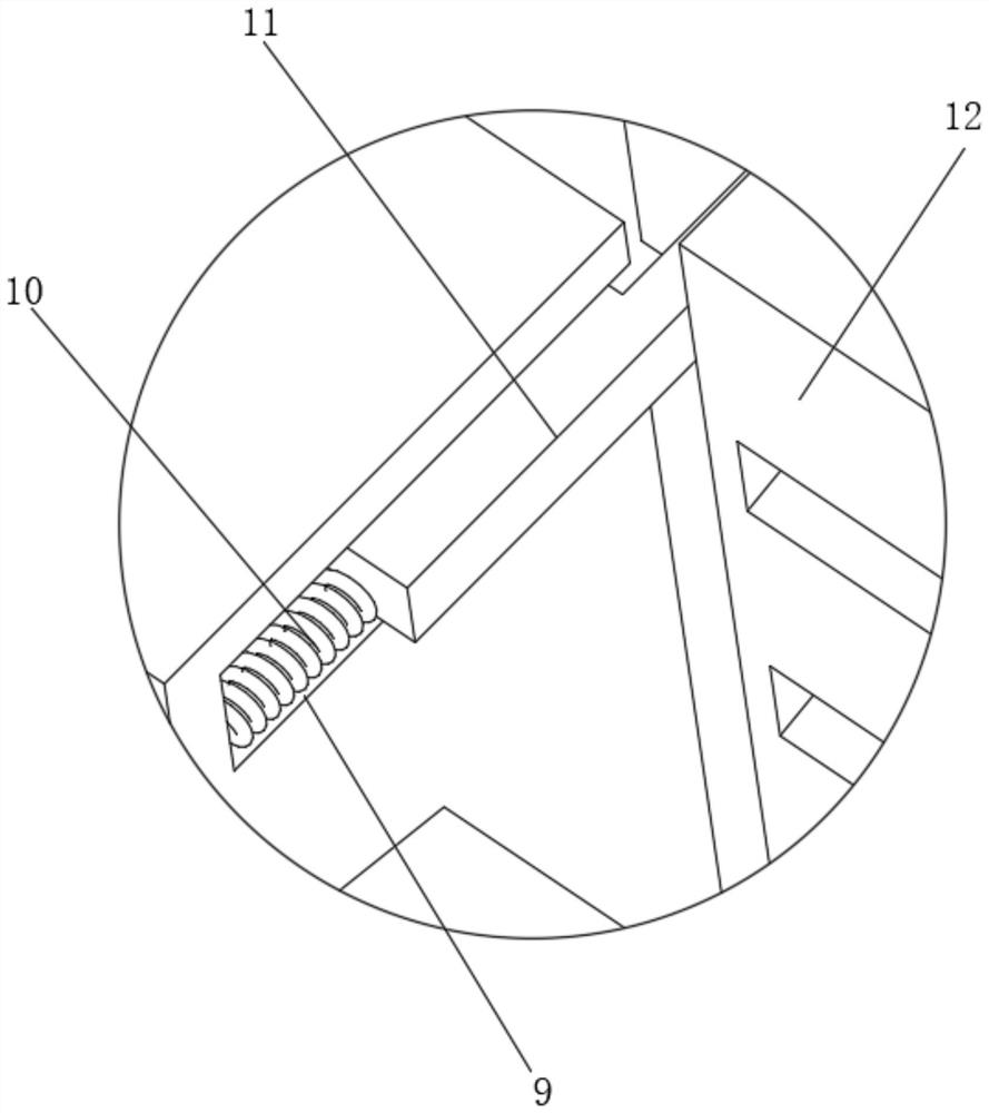
[0035] Such as Figure 1-7 As shown, the present invention provides a technical solution: a power supply system, including a power supply frame 1, a power supply controller 2 is fixedly connected to the left side inside the power supply frame 1, and the input end of the power supply controller 2 outside the power supply frame 1 is fixedly connected to There is a solar battery array 3, the top of the power supply frame 1 is fixedly connected with a heat dissipa...


PUM


Abstract

The invention discloses a power supply system which comprises a power supply frame. A power supply controller is fixedly connected to the left side in the power supply frame, a solar cell array is fixedly connected to the input end, located outside the power supply frame, of the power supply controller, and a heat dissipation top plate is fixedly connected to the top of the power supply frame; heat dissipation hole pieces are evenly arranged in the heat dissipation top plate, the back surface of the middle position in the power supply frame is fixedly connected with a standby storage battery, and conducting strips are fixedly connected to the two sides of the front surface in the power supply frame; the output end of the conducting strip at the right side is fixedly connected with a power supply transmission line, and movable inner grooves are formed in the transverse positions of the inner sides of the conducting strips; the interior of each movable inner groove is slidably connected with an adjusting insertion block through a reset spring, and one end of the back surface of the adjusting insertion block is fixedly connected with an electric connection pressing piece. The present invention relates to the technical field of power supply, and according to the power supply system and the power supply method, the active power failure is realized according to the actual environment temperature, the overheating safety of a power supply transmission structure is protected, and the fire occurrence rate is reduced.

Description

technical field [0001] The invention relates to the technical field of power supply, in particular to a power supply system and a power supply method. Background technique [0002] Power supply refers to the safe, reliable, continuous and qualified sale of electric energy to the majority of power customers through power transmission and distribution devices, so as to meet the needs of customers for economic construction and domestic electricity consumption. [0003] Electric energy is the main energy and driving force of modern industrial production. It is easy to convert from other forms of energy, and easy to convert into other forms of energy for use; its transportation and distribution are simple and economical, and it is easy to control, adjust and measure, which is conducive to the automation of the production process. Therefore, electric energy is widely used in modern industry and people's life. [0004] The traditional photovoltaic power supply system does not hav...

Claims


Application Information

Patent Timeline
IPC IPC(8): H02J7/00H02J7/35
CPCH02J7/00309H02J7/0031H02J7/0063H02J7/35
Inventor 罗嘉璐
Owner 罗嘉璐
Why Eureka
Try Eureka