Capacitor-embedded printed circuit board

A printed circuit board and circuit board technology, which is applied in the directions of printed circuit components, circuit thermal devices, electrical components, etc., can solve the problems such as the lack of attention, improvement, and high-frequency performance influence on the temperature of the circuit board, so as to improve the performance of normal use. effect of effect

Pending Publication Date: 2021-11-23
湖北中培电子科技有限公司
View PDF0 Cites 0 Cited by
  • Summary
  • Abstract
  • Description
  • Claims
  • Application Information

AI Technical Summary

Problems solved by technology

[0004] The purpose of the present invention is to solve the problem of not paying attention to the temperature inside the circuit board in the prior art, so that when the circuit board is in use, the heat accumulates, resulting in an increase in the internal temperature of the working environment. When the temperature of the printed circuit board rises beyond a certain A threshold, the circuit board performance, especially the shortcomings of high-frequency performance will be affected, and a buried capacitance printed circuit board is proposed

Method used


Image

  • Capacitor-embedded printed circuit board
  • Capacitor-embedded printed circuit board
  • Capacitor-embedded printed circuit board

Examples


Embodiment 1

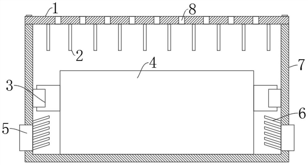
[0017] refer to figure 1 , an embedded printed circuit board, including a circuit board body 4 and a protective shell 7, the protective shell 7 can protect the circuit board body 4, and prevent the circuit board body 4 from being affected by an external force, the circuit board The main body 4 is located inside the protective shell 7, the circuit board main body 4 and the fan 5 are connected to the power supply device through wires, and an external control switch is installed on the wires.

[0018] The inner both sides lower ends of the protective shell 7 are equipped with a blower fan 5 that runs through the protective shell 7. The air outlet of the blower fan 5 is positioned at the inner side of the protective shell 7. The air outlet of the blower fan 5 is fixedly equipped with a plurality of inclined plates 6. The inclined plates 6 can Ensure that the wind blown by the fan 5 is inclined upward, and the heat generated by the circuit board body 4 is driven to the upper end of...

Embodiment 2

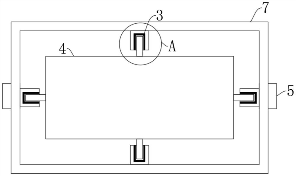
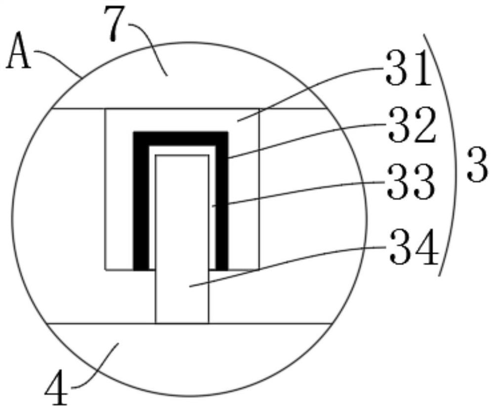
[0020] refer to Figure 1-3 The difference between this embodiment and Embodiment 1 is that multiple groups of connection structures 3 are evenly installed between the circuit board body 4 and the inner middle part of the protective shell 7, and the connection structures 3 include a fixing seat 31, a rubber pad 32, and a square groove 33 And the straight plate 34, the fixed seat 31 is installed on the inner side of the protective shell 7, the straight plate 34 is horizontally installed on one side of the circuit board body 4, the square groove 33 is vertically opened on one side of the fixed seat 31, and the straight plate 34 is inserted in the square The inner side of the groove 33, and the size of the square groove 33 matches the size of the straight plate 34, and the mutual cooperation between the straight plate 34 and the square groove 33 effectively realizes the fixing of the position of the circuit board body 4, and can be installed more quickly. Prevent the circuit boar...


PUM


Abstract

The invention relates to the technical field of circuit boards, in particular to a capacitor-embedded printed circuit board. The printed circuit board comprises a circuit board body and a protective shell; two adjacent inclined plates are arranged in parallel, a plurality of inclined plates are not in contact with the circuit board body, a plurality of through holes are distributed in a square array, a plurality of cooling fins are vertically installed at the lower end of the upper cover, the positions of the cooling fins do not coincide with the positions of the through holes, and gaps are formed between the lower ends of the cooling fins and the upper end face of the circuit board body. The fans arranged at the lower ends of the two sides of the protection shell are utilized to expel heat away from the periphery of the circuit board, the working environment in the circuit board is reduced, the high-frequency performance of the circuit board is not affected, and the normal use effect of the circuit board is improved.

Description

technical field [0001] The invention relates to the technical field of circuit boards, in particular to a capacitor-embedded printed circuit board. Background technique [0002] The names of the circuit boards are: ceramic circuit board, alumina ceramic circuit board, aluminum nitride ceramic circuit board, circuit board, PCB board, aluminum substrate, high frequency board, thick copper board, impedance board, PCB, ultra-thin circuit board, ultra-thin Thin circuit boards and printed circuit boards; [0003] When the circuit boards on the existing market are in use, they do not pay attention to the temperature inside the circuit board, so that when the circuit board is in use, the heat accumulates, resulting in an increase in the internal ambient temperature of the work. When the temperature of the printed circuit board rises beyond a certain Threshold, board performance, especially high frequency performance will be affected. Contents of the invention [0004] The purpos...

Claims


Application Information

Patent Timeline
Patent Type & Authority Applications(China)
IPC IPC(8): H05K1/02H05K7/20
CPCH05K7/20136H05K1/0203
Inventor 石教猛田绍安
Owner 湖北中培电子科技有限公司
Why Eureka
Try Eureka