Aerosol generating device with induction heating tube

An aerosol generation and induction heating technology, which is applied to tobacco and other fields, can solve the problems of low heating efficiency, hot hands, and high power consumption, and achieve the effects of increasing the heating area, good heating effect, and heat recovery

Pending Publication Date: 2021-11-26
HUIZHOU HAPPY VAPING TECH LTD
View PDF13 Cites 1 Cited by
  • Summary
  • Abstract
  • Description
  • Claims
  • Application Information

AI Technical Summary

Problems solved by technology

[0003] The existing aerosol generating device with electromagnetic induction heating generally uses an electromagnetic induction heating element to directly heat the smoking material. When directly heating, the heat gradually diffuses from the edge of the heating element to the rest of the body, requiring a large electromagnetic power Only when the temperature of the smoking substance can be raised to the set temperature, the power consumption is large, the heating efficiency is low, and the heat of the smoking substance in contact with the edge of the heating body is concentrated, which is easy to be burnt, resulting in a burnt smell in the aerosol In addition, the heating element produces a very high temperature, and if the heat insulation effect is poor, the high temperature is easy to conduct and radiate to the outer tube or housing of the aerosol generating device, and the user is likely to feel hot when using it, which brings bad use to the user. to experience

Method used


Image

  • Aerosol generating device with induction heating tube
  • Aerosol generating device with induction heating tube
  • Aerosol generating device with induction heating tube

Examples


Embodiment 1

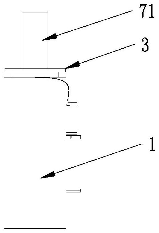
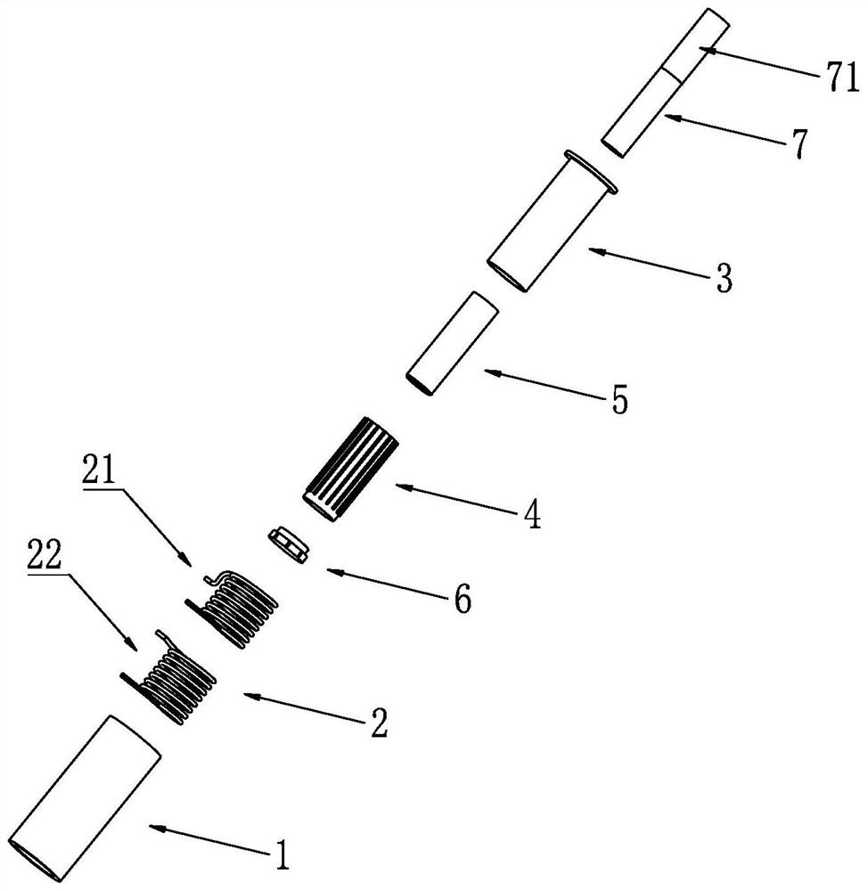
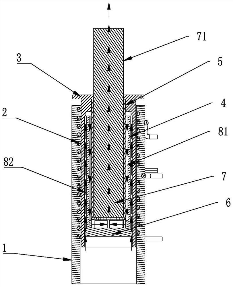
[0046] Such as Figure 1-Figure 3As shown, the present embodiment has an aerosol generating device with an induction heating tube, which is composed of an outer tube 1, an electromagnetic coil 2, an insulating tube 3, an induction heating tube 4 and an inner tube 5 from the outside to the inside, and the bottom of the insulating tube 3 is set With bottom cover6. Wherein, the interior of the inner tube 5 is provided with an inner cavity for accommodating the cigarette 7, and the electromagnetic coil 2 is axially arranged around the outer wall of the insulating tube 3, and the electromagnetic coil 2 can cause the induction heating tube 4 to generate heat when energized. The top of the cigarette 7 is a cigarette holder 71 . The outer tube 1 can be made of heat-insulating material, the insulating tube 3 can be made of heat-insulating insulating material such as PEEK plastic material, and the inner tube 5 can be made of heat-resistant non-magnetic conductive metal or non-metallic ...

Embodiment 2

[0053] Such as Figure 9-Figure 10 As shown, the present embodiment has an aerosol generating device with an induction heating tube, which is composed of an outer tube 1, an electromagnetic coil 2, an insulating tube 3, an induction heating tube 4 and an inner tube 5 from the outside to the inside, and the bottom of the insulating tube 3 is set With bottom cover6. Wherein, the interior of the inner tube 5 is provided with an inner cavity for accommodating the cigarette 7, and the electromagnetic coil 2 is axially arranged around the outer wall of the insulating tube 3, and the electromagnetic coil 2 can cause the induction heating tube 4 to generate heat when energized. The top of the cigarette 7 is a cigarette holder 71 . The outer tube 1 can be made of heat-insulating material, the insulating tube 3 can be made of heat-insulating insulating material such as PEEK plastic material, and the inner tube 5 can be made of heat-resistant non-magnetic conductive metal or non-metalli...

Embodiment 3

[0062] Such as Figure 14-Figure 15 As shown, this embodiment has an aerosol generating device with an induction heating tube, which is composed of an outer tube 1, an electromagnetic coil 2, an insulating tube 3, an induction heating tube 4, an induction heating network 9 and an inner tube 5 from the outside to the inside. A bottom cover 6 is provided at the bottom of the insulating tube 3 . Wherein, the inside of the inner tube 5 is provided with an internal cavity for accommodating the cigarette 7, and the electromagnetic coil 2 is arranged axially around the outer wall of the insulating tube 3, and the electromagnetic coil 2 can make the induction heating tube 4 and the induction heating Net 9 induces heat. The top of the cigarette 7 is a cigarette holder 71 . The outer tube 1 can be made of heat-insulating material, the insulating tube 3 can be made of heat-insulating insulating material such as PEEK plastic material, and the inner tube 5 can be made of heat-resistant n...


PUM


Abstract

The invention discloses an aerosol generating device with an induction heating tube, which comprises an outer tube, an electromagnetic coil, an insulating tube, an induction heating tube and an inner tube which are sleeved from outside to inside, and a bottom cover. The inner tube is provided with an inner cavity used for housing a solid smoke generating substance. The electromagnetic coil is arranged in a surrounding mode in the axial direction of the outer wall of the insulating tube and can enable the induction heating tube to heat when powered on to work. A plurality of outer ribs are arranged on the outer side wall of the induction heating tube in a protruding mode, a second airflow channel is formed by a gap between the insulating tube and the induction heating tube, and a first airflow channel is formed by a gap between the induction heating tube and the inner tube. When the induction heating tube emits heat, outside air sequentially enters the second airflow channel and the first airflow channel and is heated into hot airflow, and the hot airflow is gathered to the bottom of the inner tube and then upwards flows through the interior of the solid smoke generating substance to heat and bake the solidsmoke generating substance. The aerosol generating device has the beneficial effects that the heating is uniform, the airflow heating effect is better, the possibility of scorching to generate scorched smell is low, the hand scalding feeling is avoided, and the user experience is good.

Description

technical field [0001] The present invention relates to the technical field of aerosol generating devices, and more specifically, the present invention relates to an aerosol generating device with an induction heating tube. Background technique [0002] Existing cigarette sticks emit smog for the smoker to suck when the open flame burns, because the cigarette will decompose and produce multiple harmful substances such as smoke tar and carbon monoxide when the open flame burns, so smoking is harmful to health. In order to avoid a large amount of harmful substances produced by cigarettes and enjoy the unique taste of cigarettes, the function of the existing aerosol generating device is to put cigarette products or other herbal plant products in it for heating without burning when the user smokes. It is baked at a combustible temperature until it produces aerosols such as cigarette smoke. In this way, it is heated at a low temperature to emit smoke instead of burning with a hig...

Claims


Application Information

Patent Timeline
Patent Type & Authority Applications(China)
IPC IPC(8): A24F40/46
CPCA24F40/465
Inventor 林光榕郑贤彬
Owner HUIZHOU HAPPY VAPING TECH LTD
Why Eureka
Try Eureka