
Non-circular filter element material and rewinding method thereof

A non-circular, filter element technology, applied in the field of non-circular filter element core material and its rewinding, can solve the problems of inconvenient operation, difficulty in operation, dirty working environment, and excessive pause times, so as to avoid uneven products. , The operation is simple and fast, and the effect of controlling product quality

Active Publication Date: 2021-11-26
PROPURE AS
View PDF1 Cites 0 Cited by
  • Summary
  • Abstract
  • Description
  • Claims
  • Application Information

AI Technical Summary

Problems solved by technology

[0006] First, manual gluing means that the winding production of the core material cannot be fully automated. In other words, the equipment must be stopped before each core material is wound. Gluing, winding starts after gluing, the more manual work, the more pauses and the longer the pause time, thus reducing the production efficiency
[0007]Secondly, even though the end side 911 and end side 923 with narrow thickness can be glued manually, it is still inconvenient to operate and has a certain degree of difficulty. The glue speed is slow, which affects the overall efficiency
[0008]Third, manual gluing may also result in uneven quality due to different manual proficiency
[0009] Fourth, a large amount of glue is often used to seal the gap during the gluing process, but a large amount of glue is also easy to drip continuously during the gluing process Falling to the ground, in addition to causing mess and waste to the working environment, the dripping glue on the separation material may also reduce the sealing effect, so even if you want to apply more glue to strengthen the sealing effect, it will still be because the glue keeps dripping and hard to reach its purpose
[0010] Therefore, the way of gluing the ends of the two separation materials in the prior art needs to be improved.

Method used


Image

  • Non-circular filter element material and rewinding method thereof
  • Non-circular filter element material and rewinding method thereof
  • Non-circular filter element material and rewinding method thereof

Examples


Embodiment Construction

[0042] In the following, the technical means adopted by the present invention to achieve the intended purpose of the invention will be further described in conjunction with the accompanying drawings and preferred embodiments of the present invention.

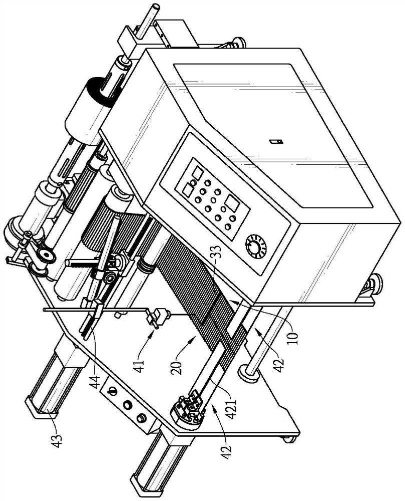
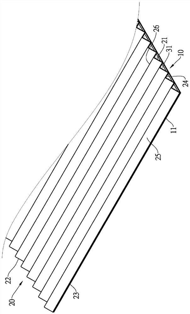
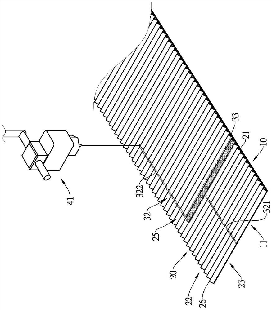
[0043] see Figure 13 As shown, the rewinding method of the non-circular filter core material of the present invention includes the following steps: combining the wave-shaped separation material and the plane separation material S1, coating the edge-sealing adhesive layer S2 and winding S3. The non-circular filter core material of the present invention preferably refers to a racetrack-shaped filter core material, but it can also be oval and other shapes, as long as it is not circular.

[0044] Combination of corrugated and flat separators S1: see figure 2 As shown, first prepare a planar separation material 10 and a wave-shaped separation material 20 for separating suspended pollutants; the side of the planar separation materi...


PUM

PropertyMeasurementUnit
widthaaaaaaaaaa

Abstract

The invention relates to a non-circular filter element material for separating suspended particles in fluid and a rewinding method of the non-circular filter element material. The rewinding method comprises the following steps of: combining a wavy separating material and a planar separating material; applying an edge sealing adhesive layer and winding. A certain amount of edge sealing adhesive layer with a certain width is applied at a first fold before winding, and then the first fold which starts winding enables the two end parts of the two separating materials to be simultaneously embedded in the edge sealing adhesive layer, so that the edge sealing adhesive layer can effectively bond the two end parts to avoid fluid bypass. As the edge sealing adhesive layer coats one side surface of the wavy separating material, even if the coating amount is large, the edge sealing adhesive layer cannot flow out easily. The operation of coating the edge sealing adhesive layer is simple and quick, the efficiency can be effectively improved, full-automatic manufacturing is facilitated, the pause frequency and time for switching to manual operation are reduced, and the efficiency is further improved.

Description

technical field [0001] The invention relates to a non-circular filter element core material for separating suspended particles in fluid and a rewinding method thereof, especially to a track-type filter element core material used for trucks and a rewinding method thereof. Background technique [0002] The filter element in the prior art includes a filter element frame and a core material installed in the filter element frame, wherein the core material includes a wave-shaped separation material and a plane separation material, and the two separation materials are interlaced and wound into a cylindrical shape, A plurality of axial passages of the same shape and size are sandwiched, half of the passages are coated with an end face sealant layer at one end of the axial direction, and the other half of the passages are coated with another end face sealant layer at the other end of the axial direction, thereby The fluid to be filtered enters the channel from one end, and after hitt...

Claims


Application Information

Patent Timeline
Patent Type & Authority Applications(China)
IPC IPC(8): B01D46/12B01D46/52B01D46/00B01D29/03
CPCB01D29/031B01D46/0001B01D46/12B01D46/527B01D2265/06B01D29/353B01D29/237
Inventor 林象济
Owner PROPURE AS
Learn More