Laser visual tracking correction method for welding of non-body external shaft of robot

A robot body and visual tracking technology, which is applied to welding equipment, welding accessories, arc welding equipment, etc., can solve the problems of many trial teaching points, the inability to obtain non-body external axis data, and the inability to use the robot's own welding seam tracking function, etc.

Pending Publication Date: 2021-11-26
TANGSHAN YINGLAI SCI & TECH
View PDF7 Cites 1 Cited by
  • Summary
  • Abstract
  • Description
  • Claims
  • Application Information

AI Technical Summary

Problems solved by technology

[0005] Aiming at the deficiencies of the prior art, the present invention provides a laser vision tracking correction method for robot non-body external axis welding. Rotat...

Method used


Image

  • Laser visual tracking correction method for welding of non-body external shaft of robot

Examples


Embodiment Construction

[0026] The following will clearly and completely describe the technical solutions in the embodiments of the present invention with reference to the accompanying drawings in the embodiments of the present invention. Obviously, the described embodiments are only some, not all, embodiments of the present invention. Based on the embodiments of the present invention, all other embodiments obtained by persons of ordinary skill in the art without making creative efforts belong to the protection scope of the present invention.

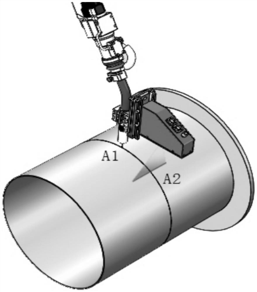
[0027] see figure 1 , the embodiment of the present invention provides a technical solution: a laser vision tracking correction method for robot non-body external axis welding, which specifically includes the following steps:

[0028] S1. Before starting welding, turn on the power, the system starts to work, and the program starts to run. Adjust the position of the welding torch at the end of the robot through the positioning function of the sensor, so that th...


PUM


Abstract

The invention discloses a laser visual tracking correction method for welding of a non-body external shaft of a robot. The laser visual tracking correction method specifically comprises the following steps that S1, before welding is started, a power source is turned on, a system starts to work, a program starts to run, the position of a welding gun at the tail end of a robot is adjusted through the position searching function of a sensor, and the tip of the welding gun at the tail end of the robot runs to a current arcing point A1. The invention relates to the technical field of welding laser correction. According to the laser visual tracking correction method for welding of the non-body external shaft of the robot, the arcing point is searched through the position searching function in the sensor, so that the tip of the welding gun at the tail end of the robot runs to the arcing point; compared with a traditional laser visual welding seam tracking system, the laser visual welding seam tracking system records the position of the robot at the arcing point and the position of the laser at the moment, and the position of the robot is compensated to realize automatic tracking of the welding gun on the welding seam position; and the laser vision welding seam tracking system has the advantages that the programming quantity is small, the system is easy to understand, and only a position searching point needs to be demonstrated.

Description

technical field [0001] The invention relates to the technical field of welding laser correction, in particular to a laser vision tracking correction method for robot non-body external axis welding. Background technique [0002] With the improvement of my country's industrial automation level, industrial robots are used more and more. Before welding production, workers need to manually control the robot to drag the welding torch according to the actual welding trajectory and welding sequence according to the specific working conditions of the welding seam. Predictive teaching, save the position information of the teaching point on the weld track. In industrial welding production, the welding environment cannot be static. The position is shifted, which affects the welding quality. In order to meet the high precision and high efficiency requirements of robot welding production, the seam tracking module based on various sensors has become a key component of the robot welding syste...

Claims


Application Information

Patent Timeline
IPC IPC(8): B23K9/127B23K9/067B23K9/32
CPCB23K9/1274B23K9/067B23K9/32
Inventor 冯海萌么文昊杨新宇李林轩张晨阳蔡建辉
Owner TANGSHAN YINGLAI SCI & TECH
Why Eureka
Try Eureka