
High-precision rapid driving mechanism for vertical shaft of numerical control machine tool

A technology of CNC machine tools and driving mechanisms, which is applied to metal processing machinery parts, maintenance and safety accessories, and metal processing equipment, etc. Problems such as large thermal deformation error, to achieve the effect of high precision and high dynamic characteristic movement, good inertia matching, and reduction of transmission clearance

Active Publication Date: 2021-11-26
通用技术集团沈阳机床有限责任公司
View PDF8 Cites 0 Cited by
  • Summary
  • Abstract
  • Description
  • Claims
  • Application Information

AI Technical Summary

Problems solved by technology

The latest requirement for high-end large-scale high-precision five-axis machine tools is to have the characteristics of high precision and high dynamic characteristics. The main equipment used in the shaping and processing of large parts in the aviation industry is a high-precision bridge-type five-axis machine tool. Usually, the vertical axis stroke is required to be greater than 2m. Repeat The positioning accuracy is less than 3 microns. The spindle box of the existing large-scale gantry five-axis machine tool mostly uses the motor to connect the screw to drive the ram to move, and the balance oil cylinder to balance the gravity of the ram. This structure has a large backlash due to the long transmission chain. The transmission chain has problems such as large thermal deformation error, and the fluctuation resistance of the balance cylinder is relatively large when moving, so the repeated positioning accuracy of the ram shaft is too poor and the dynamic performance is slightly insufficient, which cannot meet the needs of high-precision and high-dynamic response of the equipment

Method used


Image

  • High-precision rapid driving mechanism for vertical shaft of numerical control machine tool
  • High-precision rapid driving mechanism for vertical shaft of numerical control machine tool

Examples


Embodiment Construction

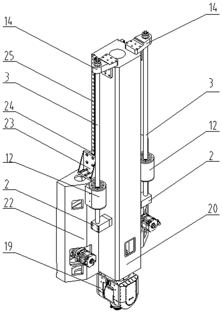
[0018] Such as figure 1 As shown, a high-precision fast drive mechanism for the vertical axis of a CNC machine tool includes a slide plate 22 and a slide rail 20, the ram 20 slides vertically along the outer surface of the slide plate 22, the bottom of the ram 20 is connected to the cutter 19, and the ram 20 The left and right sides of the ram 20 are symmetrically provided with linear guide rails 25, and the linear guide rails 25 are slidably connected with the slide plate 22; the upper support seats 14 of the screw are symmetrically arranged on the left and right sides of the top of the ram 20, and the leading screws are symmetrically arranged on the left and right sides of the middle part of the ram 20. The lower support base 2 connects the lead screw 3 between the upper support base 14 of the lead screw on the same side and the lower support base 2 of the lead screw. The lead screw 3 is a hollow structure for cooling water circulation, and each lead screw 3 is coaxially matc...


PUM


Abstract

The invention relates to a high-precision rapid driving mechanism comprises a sliding plate and a ram, the ram vertically slides along the outer surface of the sliding plate, the bottom of the ram is connected with a tool, linear guide rails are symmetrically arranged on the left side and the right side of the ram, and the linear guide rails are in sliding connection with the sliding plate; and lead screw upper supporting seats are symmetrically arranged on the left side and the right side of the top of the ram, lead screw lower supporting seats are symmetrically arranged on the left side and the right side of the middle of the ram, lead screws are connected between the lead screw upper supporting seats and the lead screw lower supporting seats on the same side, each lead screw is coaxially matched with a direct drive motor, and motor seats of the direct drive motors are connected to the sliding plate. According to the high-precision rapid driving mechanism, a transmission gap generated by gear driving is avoided, the high precision and the dynamic response speed of a transmission chain are guaranteed, and large-stroke high-precision driving is easy to achieve.

Description

technical field [0001] The invention relates to a high-precision fast driving mechanism for a vertical axis of a numerical control machine tool, belonging to the technical field of numerical control machine tool manufacturing. Background technique [0002] With the continuous development of science and technology, the requirements for large-scale high-precision bridge-type five-axis CNC machine tools in the fields of aerospace, rail transit, and military industry are also increasing. The latest requirement for high-end large-scale high-precision five-axis machine tools is to have the characteristics of high precision and high dynamic characteristics. The main equipment used in the shaping and processing of large parts in the aviation industry is a high-precision bridge-type five-axis machine tool. Usually, the vertical axis stroke is required to be greater than 2m. Repeat The positioning accuracy is less than 3 microns. The spindle box of the existing large-scale gantry five...

Claims


Application Information

Patent Timeline
IPC IPC(8): B23Q5/40B23Q11/00
CPCB23Q5/40B23Q5/402B23Q11/001B23Q11/00B23Q11/0003
Inventor 肖飞高峰白旭张广为张扬孔令友严昊明李享陈帅徐吉存戴漫一陈洪军张誉馨德懿
Owner 通用技术集团沈阳机床有限责任公司
Learn More