Novel numerical control punching and shearing tool grinding clamp

A technology for grinding jigs and scissors, which is applied in the direction of manufacturing tools, grinding workpiece supports, grinding machine parts, etc., can solve the problems of unavoidable repeated disassembly, affecting the grinding accuracy, and small contact area, so as to save grinding. time, improve grinding accuracy, and simple operation

Pending Publication Date: 2021-11-26
耿新珂
View PDF1 Cites 0 Cited by
  • Summary
  • Abstract
  • Description
  • Claims
  • Application Information

AI Technical Summary

Problems solved by technology

[0005] Although the above-mentioned patent documents can adjust the angle of the fixture by rotating the counter-rotating shaft, thereby realizing the position change of the punching scissors, which facilitates the work of the user, the following problems still exist: First, the above-mentioned patent uses an arc-shaped rotating plate to support , the contact between the rotating plate and the base is only a line contact, the contact area is too small, it will produce a large friction force during grinding, and only relying on the line contact will produce a large vibration, which will seriously affect the grinding accuracy
Second, the above-mentioned patent realizes the angle transformation of the punching and shearing tool through the rotation of the arc-shaped rotating plate, but because the arc-shaped rotating plate can only adjust the angle in a single direction, it can only form a unidirectional angle transformation for the tool. However, the position of punching and shearing tools that needs to be sharpened is often spread all over the blade body. This kind of fixture with one-way angle change still cannot avoid the problem of repeated disassembly and assembly.

Method used


Image

  • Novel numerical control punching and shearing tool grinding clamp
  • Novel numerical control punching and shearing tool grinding clamp
  • Novel numerical control punching and shearing tool grinding clamp

Examples


Embodiment Construction

[0032] The following will clearly and completely describe the technical solutions in the embodiments of the present invention with reference to the accompanying drawings in the embodiments of the present invention. Obviously, the described embodiments are only some, not all, embodiments of the present invention.

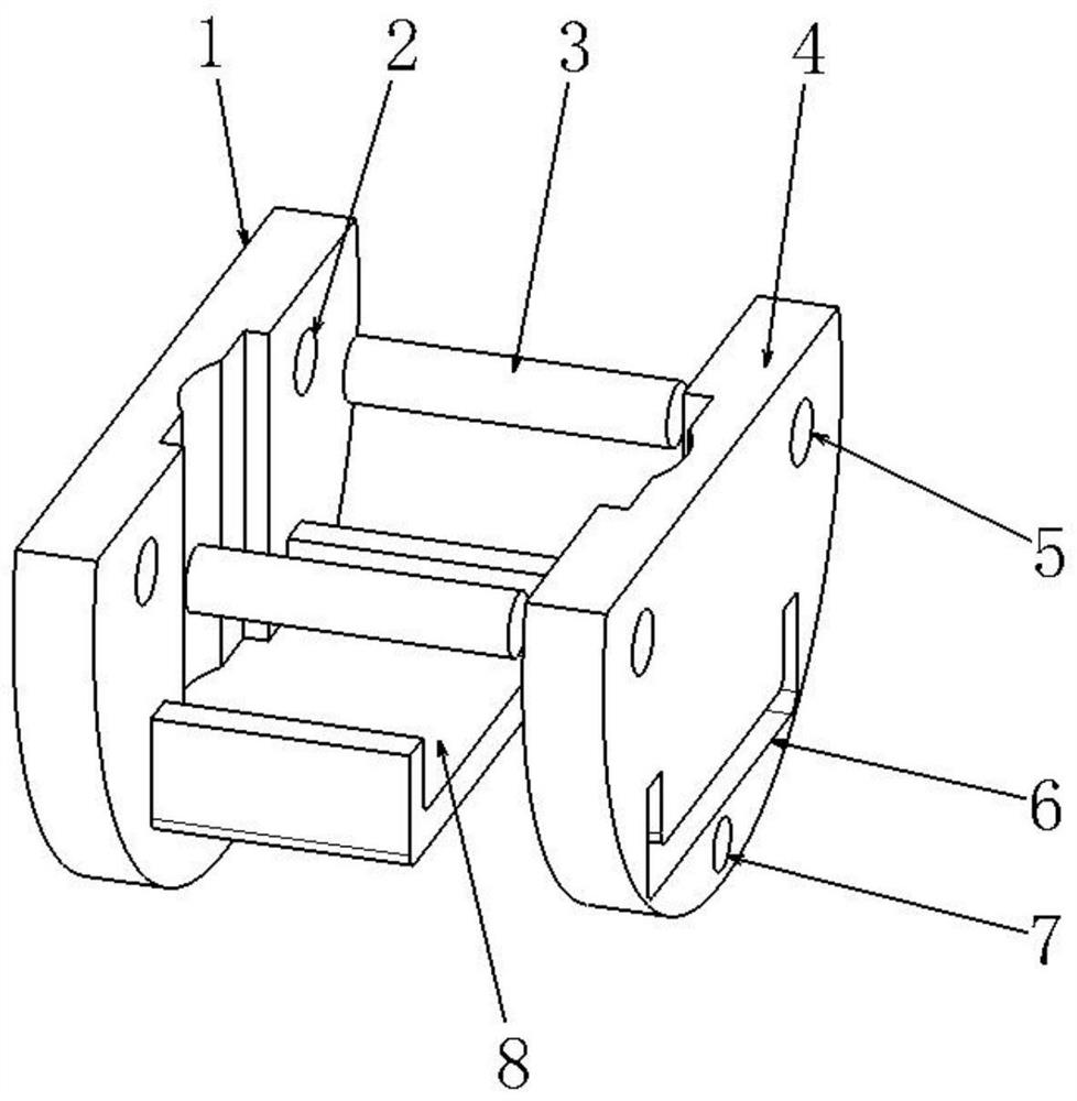
[0033] refer to figure 1 , a new type of CNC punching and shearing tool grinding fixture is to fix the tool by the extrusion action of the main clamping plate 1 and the auxiliary clamping plate 4, and the main clamping plate 1 is provided with a positioning module 8 and a guide rail threaded hole 2 , The end of the guide rail 3 is provided with threads, and the guide rail 3 is fixed on the threaded hole 2 of the guide rail through the end threads. The auxiliary clamping plate 4 is provided with a guide rail through hole 5 and an avoidance groove 6. The auxiliary clamping plate 4 can move in one direction on the guide rail 3 and the positioning module 8 through the gu...


PUM


Abstract

The invention discloses a novel numerical control punching and shearing tool grinding clamp which comprises a main clamping plate and an auxiliary clamping plate. The main clamping plate is provided with a positioning module and guide rail threaded holes, threads are arranged at the tail ends of guide rails, and the guide rails are fixed to the guide rail threaded hole through the tail end threads. According to the scheme, compared with a traditional numerical control punching and shearing tool grinding clamp, the tool axial rotation adjusting and angle adjusting functions are added, the tool setting problems during dismounting and mounting can be effectively solved, a tool can be ground in all directions through only one time of tool setting, multiple times of tool dismounting are not needed, the grinding time is saved, multiple times of tool setting are not needed, the grinding precision is improved, operation is easy, and use is convenient; and compared with the traditional technology, vibration generated during grinding can be greatly relieved, the grinding precision is improved, the axial rotation adjusting function is added in the scheme, the problem that tool setting cannot be avoided during dismounting and mounting when the angle is changed in the single direction is solved, and wide application and popularization can be achieved.

Description

technical field [0001] The invention relates to the technical field of numerical control machinery, in particular to a novel numerical control punching and shearing tool grinding fixture. Background technique [0002] In the early 1990s, the development of CNC forging punching and shearing machine tools in industrially developed countries became more and more mature, and CNC punching and shearing machine tools have entered the practical stage. Foreign technological progress has given profound inspiration to my country's CNC punching and shearing machinery industry. In the past ten years, CNC punching and shearing machine tools have been widely used in various industries, and most of them are used in the field of sheet metal processing of enterprises. CNC punching and shearing machine tools can punch out a large number of complex sheet metal parts with high precision through punching and shearing tools, which can save a lot of mold investment. [0003] Punching and shearing ...

Claims


Application Information

Patent Timeline
IPC IPC(8): B24B3/52B24B41/06B24B41/00B24B55/00
CPCB24B3/52B24B41/06B24B41/007B24B55/00
Inventor 耿新珂
Owner 耿新珂
Why Eureka
Try Eureka