Cable winding device for power transmission cable construction
A technology for power transmission cables and winding devices, applied in cleaning methods and tools, cleaning methods using tools, chemical instruments and methods, etc., can solve the problems of reduced performance, accelerated cable surface wear, and adhesion, etc., to prolong the service life , Improve performance and reduce wear
- Summary
- Abstract
- Description
- Claims
- Application Information
AI Technical Summary
Problems solved by technology
Method used
Image
Examples
Embodiment example 1
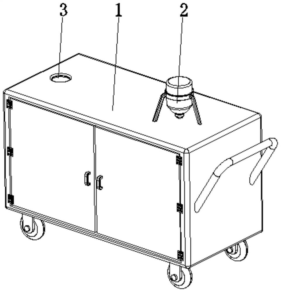
[0030] see Figure 1-6 , the present invention provides a technical solution: a cable winding device for power transmission cable construction, including a box body 1, a power mechanism 2, and a wire hole 3, the power mechanism 2 is arranged on the top side of the box body 1, and the wire hole 3 is opened On the top of the box body 1 and away from the side of the power mechanism 2;
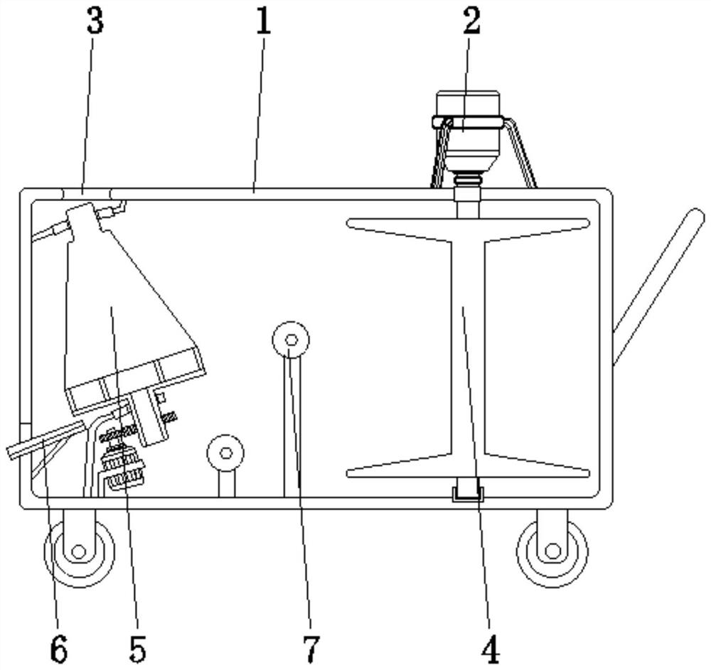
[0031] The inside of the box body 1 is provided with a winding roller 4, a debris cleaning device 5, a guide trough plate 6, and a guide roller 7, and the winding roller 4 is rotatably connected between the top and the bottom of the inner wall of the box body 1. , the top of the winding roller 4 runs through the top of the inner wall of the box body 1 and is connected with the power mechanism 2, the debris cleaning device 5 is arranged inside the box body 1 and is located directly below the wire hole 3, and the guide channel plate 6 is fixed on The inner wall of the box body 1 is close to the bot...
Embodiment example 2
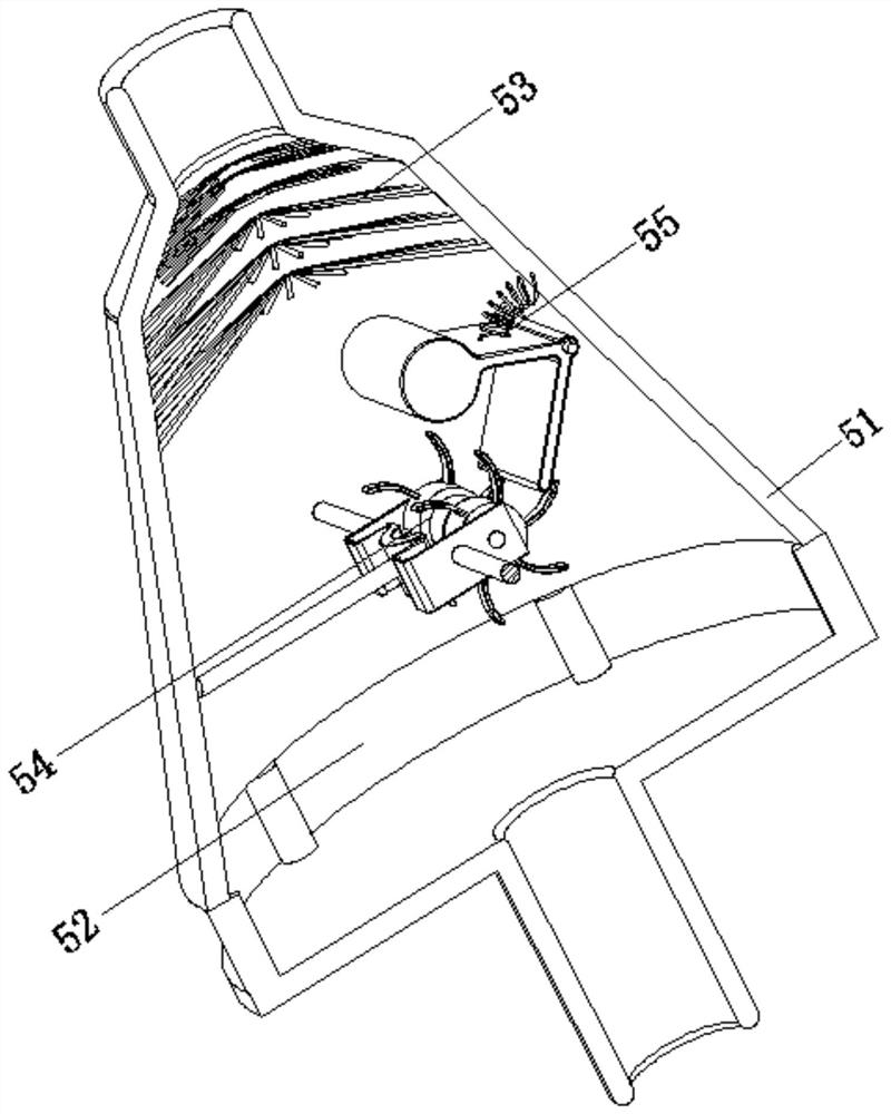
[0033] The debris cleaning device 5 is provided with a conical shell 51, a slag discharge port 52, a brush 53, a wiping device 54, and a knocking device 55. The mouth 52 is arranged on the surface bottom of the conical shell 51, the hair brush 53 is arranged on the inner wall of the conical shell 51 and near the top position, the wiping device 54 is arranged on the inner central position of the conical shell 51, and the knocking device 55 is arranged on the conical shell 51. The inner wall of the shell 51 is close to the position of the wiping device 54, and the wiping device 54 is connected with the knocking device 55. When the cable needs to be rewound, the conical shell 51 is driven by the motor, and the power mechanism 2 pairs of winding The wire roller 4 is driven to start winding, and the brush 53 will rotate with the conical shell 51 to promptly brush off the sand, small particle stones and other sundries attached to the surface of the cable, and when the cable is being ...
Embodiment example 3
[0035]The wiping device 54 is provided with a U-shaped bracket 541, a wiping pad 542, a rotating roller 543, and a dial tooth 544. The surface of the U-shaped bracket 541 is fixedly connected to the inner wall of the conical shell 51 through a connecting rod, and the wiping pad 542 is fixed on the U-shaped bracket 541. At the central position of the inner wall of the U-shaped bracket 541, the rotating roller 543 is rotatably connected between the corresponding two sides of the inner wall of the U-shaped bracket 541 and is close to the position of the wiping pad 542, and the shifting teeth 544 are fixed on the surface of the rotating roller 543. The pulling force during winding makes it move continuously, and the wiping pad 542 wipes the surface of the cable by sliding between each other. At the same time, the cable will also drive the rotation of the rotating roller 543, and the dial teeth 544 will also rotate accordingly, and then Applying the pulling force to the knocking dev...
PUM
 Abstract
Description
Claims
Application Information
 - R&D
- Intellectual Property
- Life Sciences
- Materials
- Tech Scout
- Unparalleled Data Quality
- Higher Quality Content
- 60% Fewer Hallucinations
Browse by: Latest US Patents, China's latest patents, Technical Efficacy Thesaurus, Application Domain, Technology Topic, Popular Technical Reports.
© 2025 PatSnap. All rights reserved.Legal|Privacy policy|Modern Slavery Act Transparency Statement|Sitemap|About US| Contact US: help@patsnap.com


