Lap joint structure of steel bar truss floor support plate and stiff steel-concrete beam

A steel truss and floor deck technology is applied in the field of lap joint structure of reinforced truss floor deck and stiff steel concrete beam, and can solve the problems of poor practicability of lap joint structure, reduction of space occupancy rate, large space occupancy rate, etc. , to achieve the effect of improving fire resistance and corrosion resistance, improving bearing capacity and facilitating adjustment

Inactive Publication Date: 2021-11-26
江苏腾威彩钢集团有限公司
View PDF3 Cites 0 Cited by
  • Summary
  • Abstract
  • Description
  • Claims
  • Application Information

AI Technical Summary

Problems solved by technology

[0004] The object of the present invention is to provide a lap joint structure between a reinforced truss floor deck and a stiff steel-concrete beam, which improves the stability of the lap joint by arranging the main body of the steel-concrete beam inside the main body of the floor deck. Under the premise, the space occupancy rate of the structure is reduced, and the main body of the floor deck can be pre-supported, so that the main body of the steel-concrete beam and the main body of the floor deck can be constructed normally, so as to improve work efficiency without requiring more The auxiliary parts cooperate to make the operation more convenient, and the main body of the floor deck can be jacked up, which is convenient for the user to adjust the position, improves the work efficiency, and makes the lap joint structure have a better practical effect. It solves the existing lap joint structure. The main body of the steel-concrete beam is usually directly erected on the main body of the steel-concrete beam. Therefore, the construction of the main body of the steel-concrete beam may be affected. , usually it is necessary to set up parts to strengthen it, which makes the operation more troublesome, and the steel-concrete beam body with a large cross-sectional area is required to make the space occupancy rate larger, and when the main body of the floor deck is hoisted into the device, it is easy to appear The positional deviation, because the weight of the main body of the floor deck is usually large, resulting in a waste of manpower and material resources when adjusting the position of the main body of the floor deck, making the existing lap joint structure poor in practicability

Method used


Image

  • Lap joint structure of steel bar truss floor support plate and stiff steel-concrete beam
  • Lap joint structure of steel bar truss floor support plate and stiff steel-concrete beam
  • Lap joint structure of steel bar truss floor support plate and stiff steel-concrete beam

Examples


Embodiment Construction

[0024] Next, the technical solutions in the embodiments of the present invention will be described in connection with the drawings of the embodiments of the present invention, and it is understood that the described embodiments are merely the embodiments of the present invention, not all of the embodiments. Based on the embodiments of the present invention, all other embodiments obtained by those of ordinary skill in the art are in the range of the present invention without making creative labor premise.

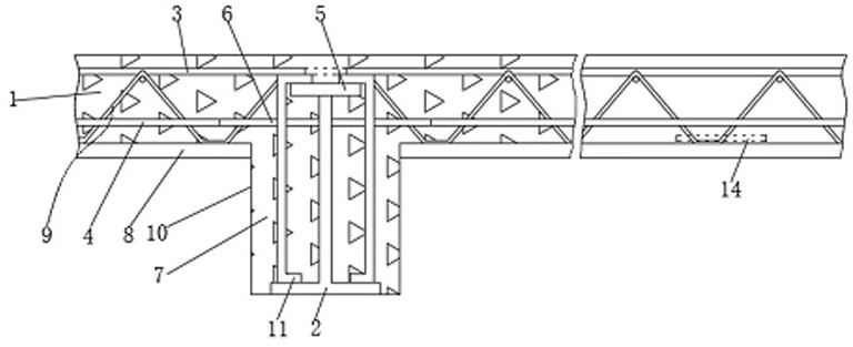
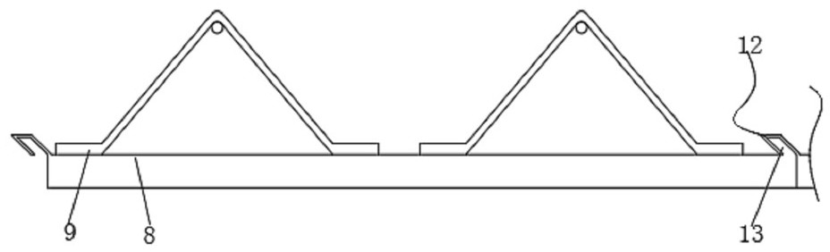
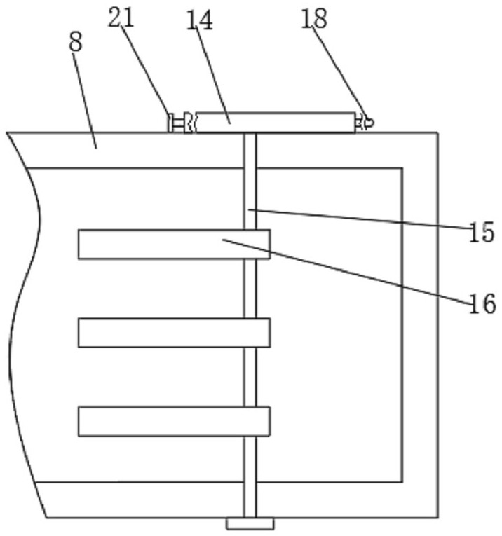
[0025] See Figure 1 to 6 The present invention provides a technical solution: a steel mixed beam lap structure of a steel truss building and a strong steel mixed beam, including the floor main body 1 and the steel mixed beam body 2, the floor body 1 includes a string steel 3, a string Reinforcing 3 and Brave Reinforced Bar 9, the steel shaped body 2 includes a upper wing portion 5, and the upper string steel 3 and the upper flap 5 are placed by the support member, and the surfac...


PUM


Abstract

The invention discloses a lap joint structure of a steel bar truss floor support plate and a stiff steel-concrete beam, and relates to the technical field of steel structure engineering. A steel-concrete beam main body is arranged inside a floor support plate main body, so that on the premise that the stability of the lap joint mode is improved, the space occupancy rate of the structure is reduced, the floor support plate main body can be supported in advance, and the steel-concrete beam main body and the floor support plate main body can be normally constructed, so that the working efficiency is improved; excessive auxiliary parts are not needed for cooperation, so that the operation is more convenient and faster; and the floor support plate main body can be jacked up, so that a user can conveniently adjust the position, the working efficiency is improved, and the lap joint structure has the effect of better practicability.

Description

Technical field [0001] The present invention relates to the technical field of steel structural engineering, and is specifically a reinforced truss floor and a strong steel mixed beam lap structure. Background technique [0002] The reinforced truss floor is to processes the steel bars in the floor into a steel truss, and fit the substrate made of the bottom plate, and form a stable support structure with the strong steel mixed beam. [0003] At present, the existing lap structure, the main body of the steel grounding is usually directly on the main body of the steel-shaped member, so there may be a case where the main body of the steel mixed beam may occur, and when the main body of the steel mixed beam is directly placed on the steel laminate body, It is usually necessary to set the component to enhance the processing, which makes it more troublesome, and the main body that requires a large cross-sectional area larger has a large space occupancy rate, and when the support body ...

Claims


Application Information

Patent Timeline
Patent Type & Authority Applications(China)
IPC IPC(8): E04B5/23E04B5/38E04C5/065E04C3/293E04G21/18
CPCE04B5/23E04B5/38E04C5/0656E04C3/293E04G21/1841
Inventor 浑林林
Owner 江苏腾威彩钢集团有限公司
Why Eureka
Try Eureka